Product Description
Characteristics
Excellent ecological design adds luster to your brand image.
Various Product input,output and mounting design to meet your diverse needs.
The FEA design of the casting housing,which improves the running stability by 30% and effectively reduces the noise of the whole machine.
High precision worm hob is used to process worm gear,which optimizes contact area,ensures lower noise and longer lifespan.
Excellent material and heat treatment process improve products reliability and lifespan.
High reliability and long design life can effectively reduce your use and maintenance costs.
Unique modular design,international production ,faster production and delivery.
Product type
Mounting mode:foot mounted, flange mounted, torque arm mounted.
Output shaft: CHINAMFG shaft, hollow shaft
RFQ
Q:Are you trading company or manufacturer?
A: We are manufacturer with over 20 years' experience.
Q: How long is your delivery time?
A: Generally it is within 10 days if the goods are in stock, for goods produced as per order, it is within 35 days after confirmation of order.
Q: How long should I wait for the feedback after I send the enquiry?
A: Normally within 12 hours.
Q: What information should I give you to confirm the product?
A: Model/Size, Transmission Ratio, Speed, Shaft directions & Order quantity etc.
Q: Hong long is your product warranty?
A: We offer 12 months warranty from departure date of the goods.
Q: What is your payment terms? T/T 100% in advance for amount less than USD10000.-, 30% T/T in advance , balance before shipment for amount above USD10000.
If you have any other questions, please feel free to contact us below:
HOW TO CONTACT US?
Send your Inquiry Details in the Below, click "Send" Now! /* January 22, 2571 19:08:37 */!function(){function s(e,r){var a,o={};try{e&&e.split(",").forEach(function(e,t){e&&(a=e.match(/(.*?):(.*)$/))&&1
| Application: | Motor, Machinery |
|---|---|
| Function: | Change Drive Torque, Change Drive Direction, Speed Changing, Speed Reduction |
| Layout: | Right Angle |
| Hardness: | Hardened Tooth Surface |
| Installation: | Horizontal Type |
| Step: | Single-Step |
| Customization: |
Available
| Customized Request |
|---|
Using NMRV Gearboxes in High-Load Applications
NMRV gearboxes can be used in moderate to high-load applications, but their load capacity is generally limited compared to some other gearbox types. They are best suited for applications with light to moderate loads, such as conveyor systems, packaging equipment, and small machinery. It's important to consider the specific load requirements and consult with gearbox manufacturers or engineers to ensure the chosen NMRV gearbox can handle the intended application's load demands.
Lifespan of an NMRV Gearbox
The lifespan of an NMRV (worm gear) gearbox can vary based on several factors, including the quality of manufacturing, proper maintenance practices, operating conditions, and the specific application it is used for. However, when designed, manufactured, and maintained properly, NMRV gearboxes can have a long and reliable service life.
High-quality NMRV gearboxes that are made from durable materials, precisely machined, and assembled with care tend to have a longer lifespan. Regular maintenance, including proper lubrication, inspection, and addressing any signs of wear or damage, can significantly extend the gearbox's operational life.
The operating conditions in which the gearbox is used also play a role in determining its lifespan. Factors such as load, temperature, speed, and environment can impact the wear and tear on the gearbox components.
It's important to follow the manufacturer's recommendations for maintenance intervals and procedures to ensure optimal performance and longevity of the NMRV gearbox. By adhering to these guidelines and addressing any issues promptly, users can expect an NMRV gearbox to provide reliable service for many years.
Choosing the Right Size NMRV Gearbox for Your Application
Selecting the appropriate size NMRV gearbox for your application involves considering several important factors:
- Input Power: Determine the power requirement of your application, including both the input speed and the required output torque.
- Service Factor: Take into account any potential overloads or unexpected conditions that may occur during operation. Applying a service factor ensures the gearbox can handle occasional peak loads.
- Output Speed: Calculate the desired output speed of the gearbox. This is crucial for ensuring the gearbox meets the requirements of your application.
- Operating Conditions: Consider the environmental conditions in which the gearbox will operate, including temperature, humidity, and exposure to dust or chemicals.
- Mounting and Space: Evaluate the available space for mounting the gearbox and ensure it fits within the allotted dimensions.
- Shaft Configuration: Determine whether the gearbox requires a specific shaft configuration or if additional components such as couplings are needed.
- Application Type: Consider the type of application the gearbox will be used in, such as conveyor systems, agitators, mixers, or other specific applications.
- Load Characteristics: Analyze the load characteristics, including the type of load (constant, intermittent, shock), to ensure the gearbox can handle the load variations.
It's essential to work closely with gearbox manufacturers or distributors who can provide technical support and assist in selecting the right size NMRV gearbox based on your specific application requirements.


editor by CX 2024-04-30
China factory Nmrv Series Nmrv063 030 075 090 Gear Box Aluminum Cast Iron Wheel Reduction Drive Speed Motor Worm Reducer Gearbox bevel gearbox
Product Description
High Torque Nmrv Series Gear Box Aluminum Cast Iron Wheel Reduction Power Transmission Drive Speed Worm Gear Reducer Gearbox
Product Description
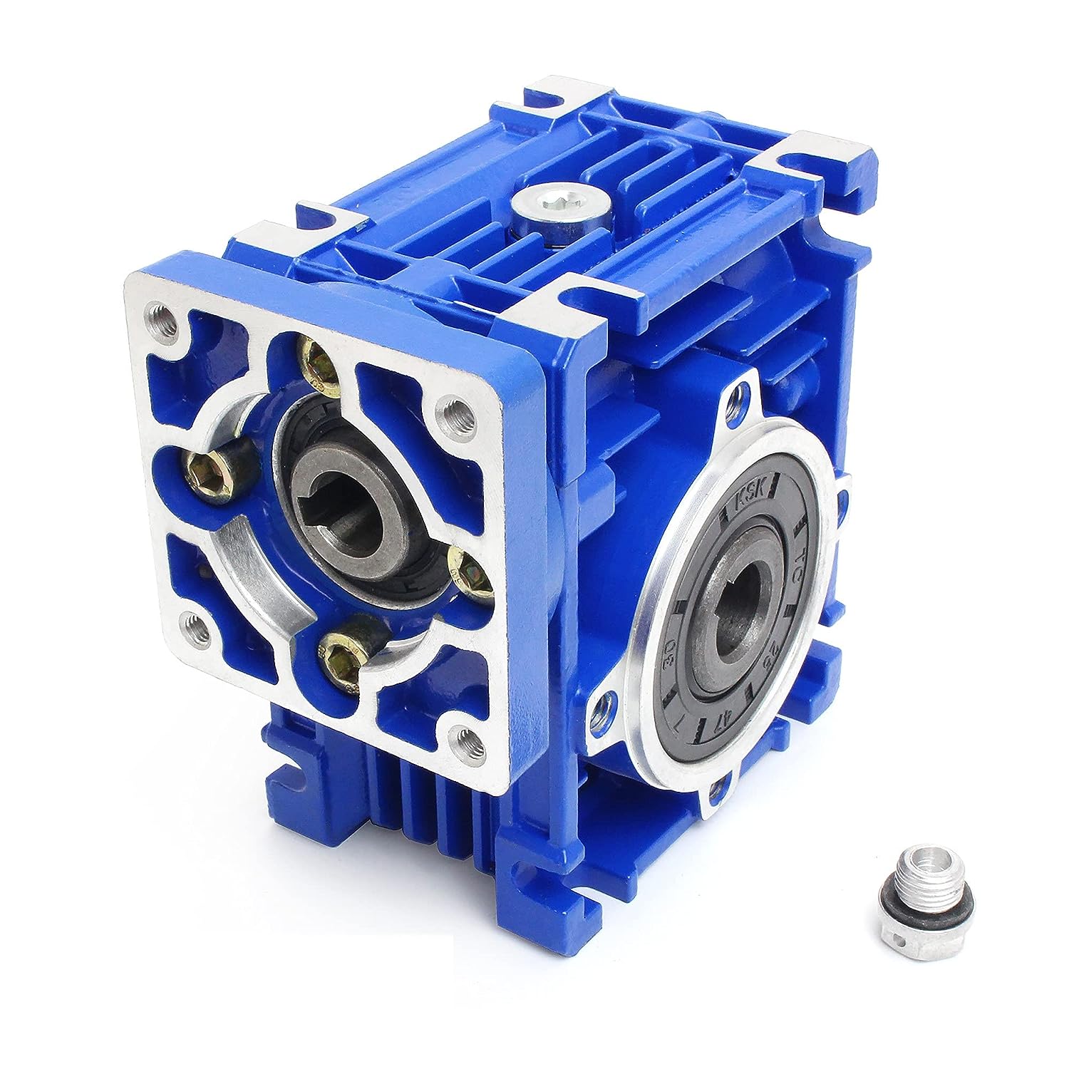
Worm gearbox
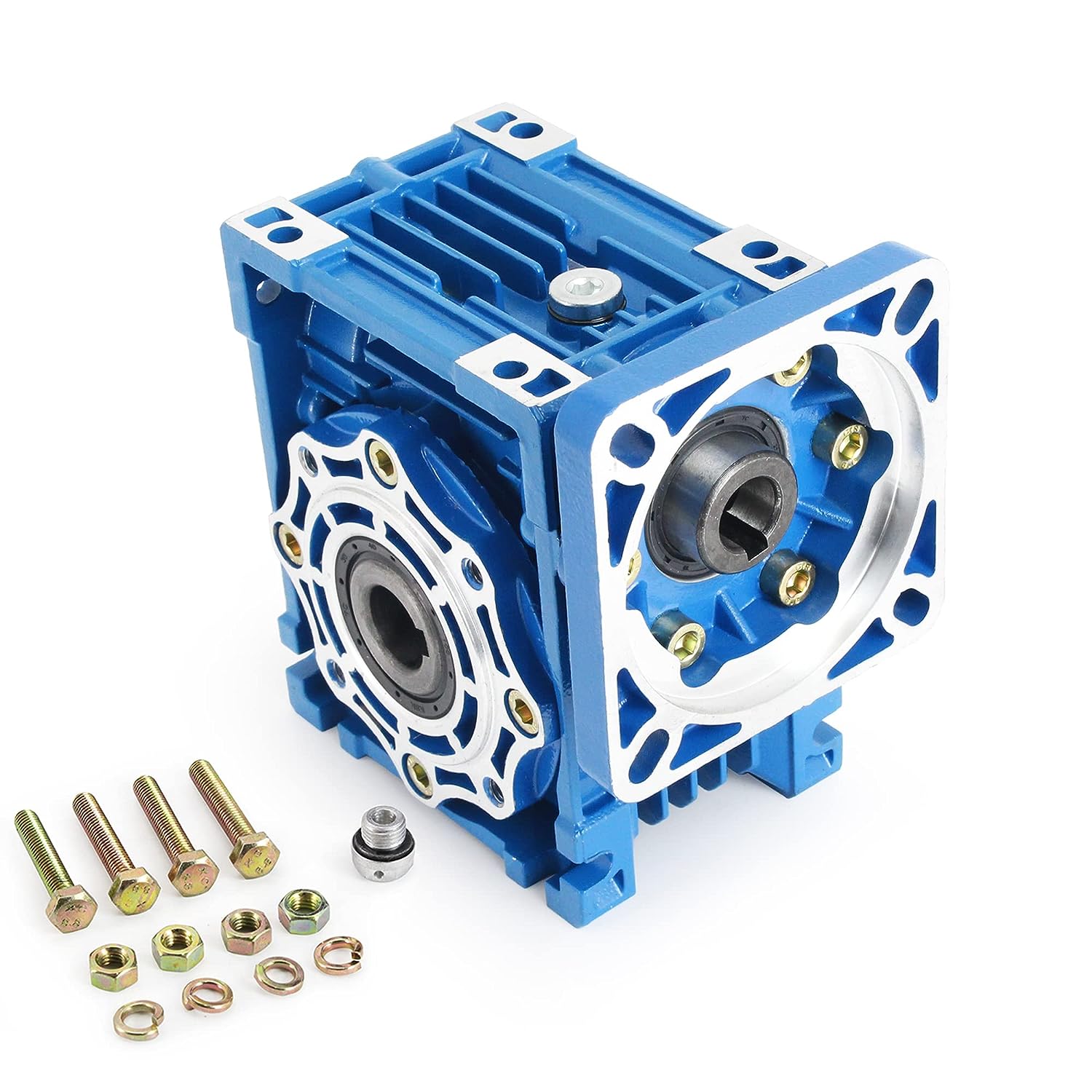
Shell: aluminum alloy (base: 571-090) cast iron (base: 110-150);
Worm: 20Cr steel. Carbonitriding treatment (after fine grinding, keep the hardness of tooth surface HRC60, and the hardness thickness is greater than 0.5mm);
Worm gear: wear-resistant nickel bronze with special configuration;
Model: RV25 RV30 RV40 RV50 RV63 RV75 RV90 RV110 RV130 RV150 NMRV25 NMRV30 NMRV40 NMRV50 NMRV63 NMRV75 NMRV90 NMRV110 NMRV130 NMRV150
NRV25 NRV30 NRV40 NRV50 NRV63 NRV75 NRV90 NRV110 NRV130 NRV150
Characteristic 1. Compact mechanical structure, light volume and shape, small size and high efficiency; 2. Good heat exchange performance and fast heat dissipation; 3. Simple installation, flexibility, superior performance and easy maintenance; 4. Stable operation, low noise, durable; 5. Strong usability, high safety and reliability;
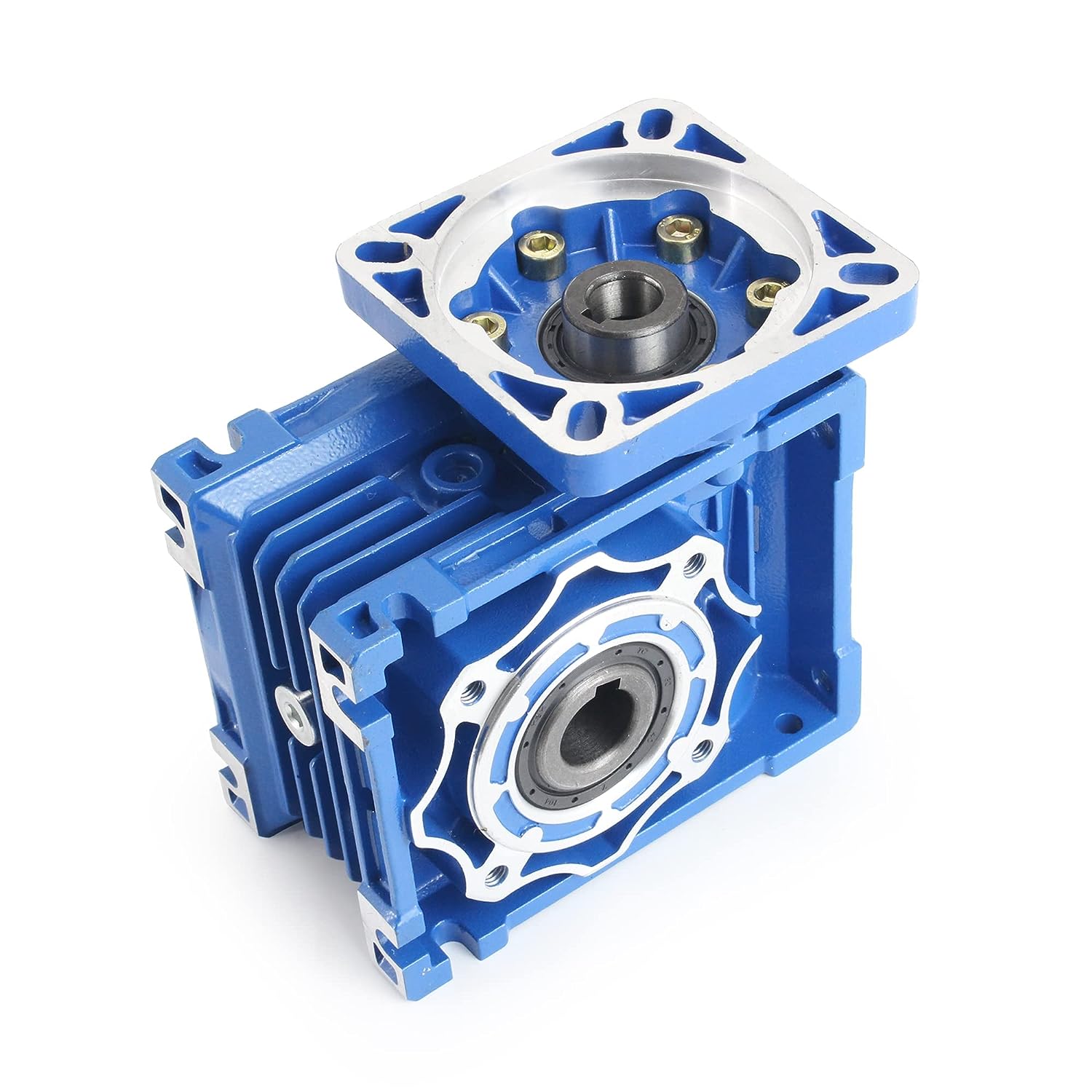
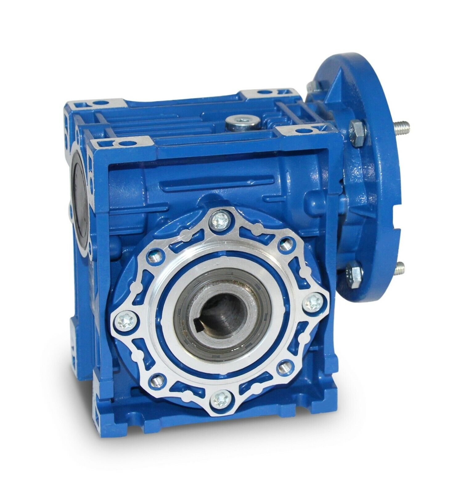
NMRV Worm Gearbox with Output Flange |
NRV-F Single CHINAMFG Shaft Input Worm Gearbox with Square Flange Output |
NRV-VS Dual CHINAMFG Shaft Input Worm Gearbox with Flange Output |
NRV Shaft Input Worm Gearbox |
NMRV-VS Dual Input Worm Gearbox with IEC Motor Flange |
NMRV-F Worm Gearbox with Flange Output |
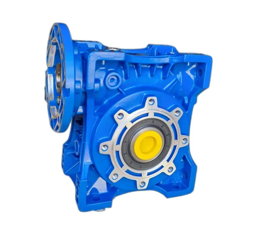
PC+NMRV Worm Gearbox with PC Gear Unit |
NMRV+NMRV |
Related products
1. The wide and comprehensive range of N series for industrial applications
2. Low-speed shaft design: Cylindrical with key, splined, hollow with shrink disc or splined hollow shaft
3. Rigid and precise nodular cast iron casing
4. Low noise running, high manufacturing quality standard
5. High and reliable performance, load capacity and low-speed shaft bearing
Please click here for more types!
Company Profile
Our Services
With all our activities DNV-ISO 9001, SGS -certified, we stand for top-quality service. Entrusting your gearboxes to the care of our Services.
Help protect your gearbox from wear and grinding, SGR gearbox converts torque reliably and efficiently.
We customize our CHINAMFG planetary gear units, double enveloping worm gearbox, helical gear motor, modular design helical gear unit, worm gearbox, cycloidal gearbox etc to fit your application and meet your needs.
These features enable a reliable and safe service life of over 200 000 operational hours.
Our customers have been placing their trust in CHINAMFG gear units since 1997. More than 500 000 gear units of our gearbox are in use reliably around the world, in many cases under very harsh conditions.
Related Products
For more reducers and mechanical accessories, please click here to view
/* January 22, 2571 19:08:37 */!function(){function s(e,r){var a,o={};try{e&&e.split(",").forEach(function(e,t){e&&(a=e.match(/(.*?):(.*)$/))&&1
| Application: | Motor, Electric Cars, Motorcycle, Machinery, Marine, Toy, Agricultural Machinery, Car |
|---|---|
| Function: | Distribution Power, Speed Changing, Speed Reduction |
| Layout: | Wrom |
| Hardness: | Hardened Tooth Surface |
| Installation: | Worm Reducer |
| Step: | Worm Drive |
| Customization: |
Available
| Customized Request |
|---|
Troubleshooting Abnormal Noises in an NMRV Gearbox
Abnormal noises from an NMRV gearbox can be troublesome and might indicate underlying issues. Follow these steps to troubleshoot and resolve the problem:
- Identify the Noise: Listen closely to the noise and determine if it's a grinding, whining, or knocking sound.
- Check Lubrication: Insufficient or contaminated lubrication can lead to noises. Ensure the gearbox is properly lubricated.
- Inspect Gears: Examine the gear teeth for wear, damage, or misalignment.
- Look for Foreign Objects: Foreign objects inside the gearbox can cause noise. Clean and inspect the interior.
- Check Bearings: Worn or damaged bearings can be noisy. Inspect and replace them if necessary.
- Inspect Seals: Damaged seals can allow contaminants in, affecting performance. Replace damaged seals.
- Examine Housing: Ensure the gearbox housing is intact without cracks or misalignment.
- Review Load Conditions: Excessive loads can lead to noise. Ensure the gearbox isn't overloaded.
- Check Mounting: Confirm the gearbox is properly mounted and aligned.
- Consult Guidelines: Refer to manufacturer guidelines for specific troubleshooting steps.
- Professional Help: If the issue persists, seek help from a professional technician or manufacturer.
Follow these steps to identify and rectify abnormal noises in your NMRV gearbox.
Lifespan of an NMRV Gearbox
The lifespan of an NMRV (worm gear) gearbox can vary based on several factors, including the quality of manufacturing, proper maintenance practices, operating conditions, and the specific application it is used for. However, when designed, manufactured, and maintained properly, NMRV gearboxes can have a long and reliable service life.
High-quality NMRV gearboxes that are made from durable materials, precisely machined, and assembled with care tend to have a longer lifespan. Regular maintenance, including proper lubrication, inspection, and addressing any signs of wear or damage, can significantly extend the gearbox's operational life.
The operating conditions in which the gearbox is used also play a role in determining its lifespan. Factors such as load, temperature, speed, and environment can impact the wear and tear on the gearbox components.
It's important to follow the manufacturer's recommendations for maintenance intervals and procedures to ensure optimal performance and longevity of the NMRV gearbox. By adhering to these guidelines and addressing any issues promptly, users can expect an NMRV gearbox to provide reliable service for many years.
Installing an NMRV Gearbox
Installing an NMRV gearbox requires careful attention to ensure proper alignment and secure attachment. Here's a general guide to the installation process:
- Prepare the Workspace: Ensure you have a clean and organized workspace with the necessary tools and equipment.
- Positioning: Place the NMRV gearbox in the desired position on your machinery, making sure it aligns with the input and output components.
- Alignment: Ensure that the input shaft of the gearbox is aligned with the driving shaft from the power source. Misalignment can lead to premature wear and reduced efficiency.
- Mounting: Securely mount the NMRV gearbox to the machinery frame using appropriate fasteners. Follow the manufacturer's recommendations for torque specifications.
- Input Coupling: Connect the input shaft of the gearbox to the driving shaft using a suitable coupling. This coupling should be properly aligned to avoid unnecessary stress on the gearbox components.
- Output Coupling: Similarly, connect the output shaft of the gearbox to the driven component using an appropriate coupling.
- Lubrication: Before operation, make sure to fill the gearbox with the recommended lubricant to ensure proper gear meshing and reduce friction.
- Testing: Run the machinery briefly to check for any unusual noises, vibrations, or leaks. Make any necessary adjustments.
It's crucial to follow the manufacturer's installation guidelines and specifications to ensure a smooth and trouble-free installation process. Proper installation contributes to the longevity and reliable performance of your NMRV gearbox.
editor by CX 2024-04-25
China factory Nmrv Cast Iron Case Worm Gearbox automatic gearbox
Product Description
RV series Characteristics
- RV - Sizes:--150
- Input Options: with input shaft, With Square flange,With Input Flange
- Input Power 0.06 to 11 kW
- RV-Size from 030 to 105 in die-cast aluminium alloy budy and over 110 in cast iron
- Ratios between 5 and 100
- Max torque 1550 N.m and admissible output radial loads max 8771 N
- Aluminium units are supplied complete with synthetic oil and allow for universal mounting positions, with no need to modify lubricant quantity
- Worm wheel: Copper (KK Cu).
- Loading capacity in accordance with: ISO 9001:2015/GB/T 19001-2016
- Size 030 and over are painted with RAL 5571 blue
- Worm gear reducers are available with diffferent combinations: NMRV+NMRV, NMRVpower+NMRV, JWB+NMRV
- NMRV, NRV+VS,NMRV+AS,NMRV+VS,NMRV+F
- Options: torque arm, output flange, viton oil seals, low/high temperature oil, filling/drain/breather/level plug,Small gap
Basic models can be applied to a wide range of power reduction ratios from 5 to 1000.
Warranty: One year from date of delivery.
| WORM GEARBOX | |||||
| SNW SERIES | Output Speed Range: | ||||
| Type | Old Type | Output Torque | Output Shaft Dia. | 14rpm-280rpm | |
| SNW030 | RV030 | 21N.m | φ14 | Applicable Motor Power: | |
| SNW040 | RV040 | 45N.m | φ19 | 0.06kW-11kW | |
| SNW050 | RV050 | 84N.m | φ25 | Input Options1: | |
| SNW063 | RV063 | 160N.m | φ25 | With Inline AC Motor | |
| SNW075 | RV075 | 230N.m | φ28 | Input Options2: | |
| SNW090 | RV090 | 410N.m | φ35 | With Square flange | |
| SNW105 | RV105 | 630N.m | φ42 | Input Options3: | |
| SNW110 | RV110 | 725N.m | φ42 | With Input Shaft | |
| SNW130 | RV130 | 1050N.m | φ45 | Input Options4: | |
| SNW150 | RV150 | 1550N.m | φ50 | With Input Flange |
Starshine Drive
ZheJiang CHINAMFG Drive Co.,Ltd,the predecessor was a state-owned military mould enterprise, was established in 1965. CHINAMFG specializes in the complete power transmission solution for high-end equipment manufacturing industries based on the aim of "Platform Product, Application Design and Professional Service".
CHINAMFG have a strong technical force with over 350 employees at present, including over 30 engineering technicians, 30 quality inspectors, covering an area of 80000 square CHINAMFG and kinds of advanced processing machines and testing equipments. We have a good foundation for the industry application development and service of high-end speed reducers & variators owning to the provincial engineering technology research center,the lab of gear speed reducers, and the base of modern R&D.
Our Team
Quality Control
Quality:Insist on Improvement,Strive for Excellence With the development of equipment manufacturing indurstry,customer never satirsfy with the current quality of our products,on the contrary,wcreate the value of quality.
Quality policy:to enhance the overall level in the field of power transmission
Quality View:Continuous Improvement , pursuit of excellence
Quality Philosophy:Quality creates value
3. Incoming Quality Control
To establish the AQL acceptable level of incoming material control, to provide the material for the whole inspection, sampling, immunity. On the acceptance of qualified products to warehousing, substandard goods to take return, check, rework, rework inspection; responsible for tracking bad, to monitor the supplier to take corrective measures
to prevent recurrence.
4. Process Quality Control
The manufacturing site of the first examination, inspection and final inspection, sampling according to the requirements of some projects, judging the quality change trend;
found abnormal phenomenon of manufacturing, and supervise the production department to improve, eliminate the abnormal phenomenon or state.
5. FQC(Final QC)
After the manufacturing department will complete the product, stand in the customer's position on the finished product quality verification, in order to ensure the quality of
customer expectations and needs.
6. OQC(Outgoing QC)
After the product sample inspection to determine the qualified, allowing storage, but when the finished product from the warehouse before the formal delivery of the goods, there is a check, this is called the shipment inspection.Check content:In the warehouse storage and transfer status to confirm, while confirming the delivery of the product
is a product inspection to determine the qualified products.
Packing
Delivery
/* January 22, 2571 19:08:37 */!function(){function s(e,r){var a,o={};try{e&&e.split(",").forEach(function(e,t){e&&(a=e.match(/(.*?):(.*)$/))&&1
| Hardness: | Hardened Tooth Surface |
|---|---|
| Installation: | Horizontal, Vertical |
| Layout: | Coaxial |
| Gear Shape: | Conical - Cylindrical Gear |
| Step: | Single-Step |
| Type: | Worm Reducer |
| Customization: |
Available
| Customized Request |
|---|
Using NMRV Gearboxes in High-Load Applications
NMRV gearboxes can be used in moderate to high-load applications, but their load capacity is generally limited compared to some other gearbox types. They are best suited for applications with light to moderate loads, such as conveyor systems, packaging equipment, and small machinery. It's important to consider the specific load requirements and consult with gearbox manufacturers or engineers to ensure the chosen NMRV gearbox can handle the intended application's load demands.
Maintenance and Service of an NMRV Gearbox
Maintaining and servicing an NMRV (worm gear) gearbox is essential to ensure its proper functioning, longevity, and reliability. Here are the steps and practices involved in maintaining and servicing an NMRV gearbox:
- Lubrication: Regularly lubricate the gearbox as per the manufacturer's recommendations. Use the appropriate lubricant to ensure smooth operation and to reduce friction and wear between the gear components.
- Inspection: Periodically inspect the gearbox for any signs of wear, damage, or leaks. Check for unusual noises, vibrations, or overheating during operation.
- Cleaning: Keep the gearbox and its surrounding area clean to prevent the buildup of dirt, debris, or contaminants that could potentially affect its performance.
- Tighten Fasteners: Check and tighten any fasteners, bolts, or screws that might have loosened due to vibrations during operation.
- Seal Inspection: Examine the seals and gaskets for signs of wear or leakage. Replace them if necessary to prevent oil leaks or ingress of contaminants.
- Temperature Monitoring: Monitor the operating temperature of the gearbox. Excessive heat can lead to premature wear and damage. Ensure proper ventilation and cooling if required.
- Address Issues Promptly: If you notice any unusual behavior, noise, or performance issues with the gearbox, address them promptly. Ignoring problems can lead to more significant damage over time.
- Replace Worn Parts: If any components, such as gears, bearings, or seals, are worn or damaged, replace them with genuine manufacturer-approved parts.
- Professional Service: For more extensive servicing, repairs, or overhauls, consult a professional with expertise in gearbox maintenance. They can disassemble, inspect, and reassemble the gearbox accurately.
By following these maintenance and servicing practices, you can ensure that your NMRV gearbox remains in optimal condition, delivering reliable performance and an extended operational lifespan.
Installing an NMRV Gearbox
Installing an NMRV gearbox requires careful attention to ensure proper alignment and secure attachment. Here's a general guide to the installation process:
- Prepare the Workspace: Ensure you have a clean and organized workspace with the necessary tools and equipment.
- Positioning: Place the NMRV gearbox in the desired position on your machinery, making sure it aligns with the input and output components.
- Alignment: Ensure that the input shaft of the gearbox is aligned with the driving shaft from the power source. Misalignment can lead to premature wear and reduced efficiency.
- Mounting: Securely mount the NMRV gearbox to the machinery frame using appropriate fasteners. Follow the manufacturer's recommendations for torque specifications.
- Input Coupling: Connect the input shaft of the gearbox to the driving shaft using a suitable coupling. This coupling should be properly aligned to avoid unnecessary stress on the gearbox components.
- Output Coupling: Similarly, connect the output shaft of the gearbox to the driven component using an appropriate coupling.
- Lubrication: Before operation, make sure to fill the gearbox with the recommended lubricant to ensure proper gear meshing and reduce friction.
- Testing: Run the machinery briefly to check for any unusual noises, vibrations, or leaks. Make any necessary adjustments.
It's crucial to follow the manufacturer's installation guidelines and specifications to ensure a smooth and trouble-free installation process. Proper installation contributes to the longevity and reliable performance of your NMRV gearbox.
editor by CX 2024-04-08
China 140 ratio speed reducer gear box wrom gear reduction cast iron worm gearbox
Error:获取session失败,

What is a worm gear reducer gearbox?
A worm gear reducer gearbox is a mechanical device that uses a worm gear and a worm to reduce the speed of a rotating shaft. The gear reducer gearbox can increase the output torque of the engine according to the gear ratio. This type of gear reducer gearbox is characterized by its flexibility and compact size. It also increases the strength and efficiency of the drive.
Hollow shaft worm gear reducer gearbox
The hollow shaft worm gear reducer gearbox is an additional output shaft connecting various motors and other gearboxes. They can be installed horizontally or vertically. Depending on size and scale, they can be used with gearboxes from 4GN to 5GX.
Worm gear reducer gearboxes are usually used in combination with helical gear reducer gearboxes. The latter is mounted on the input side of the worm gear reducer gearbox and is a great way to reduce the speed of high output motors. The gear reducer gearbox has high efficiency, low speed operation, low noise, low vibration and low energy consumption.
Worm gear reducer gearboxes are made of hard steel or non-ferrous metals, increasing their efficiency. However, gears are not indestructible, and failure to keep running can cause the gear oil to rust or emulsify. This is due to moisture condensation that occurs during the operation and shutdown of the reducer gearbox. The assembly process and quality of the bearing are important factors to prevent condensation.
Hollow shaft worm gear reducer gearboxes can be used in a variety of applications. They are commonly used in machine tools, variable speed drives and automotive applications. However, they are not suitable for continuous operation. If you plan to use a hollow shaft worm gear reducer gearbox, be sure to choose the correct one according to your requirements.
Double throat worm gear
Worm gear reducer gearboxes use a worm gear as the input gear. An electric motor or sprocket drives the worm, which is supported by anti-friction roller bearings. Worm gears are prone to wear due to the high friction in the gear teeth. This leads to corrosion of the confinement surfaces of the gears.
The pitch diameter and working depth of the worm gear are important. The pitch circle diameter is the diameter of the imaginary circle in which the worm and the gear mesh. Working depth is the maximum amount of worm thread that extends into the backlash. Throat diameter is the diameter of the circle at the lowest point of the worm gear face.
When the friction angle between the worm and the gear exceeds the lead angle of the worm, the worm gear is self-locking. This feature is useful for lifting equipment, but may be detrimental to systems that require reverse sensitivity. In these systems, the self-locking ability of the gears is a key limitation.
The double throat worm gear provides the tightest connection between the worm and the gear. The worm gear must be installed correctly to ensure maximum efficiency. One way to install the worm gear assembly is through a keyway. The keyway prevents the shaft from rotating, which is critical for transmitting torque. Then attach the gear to the hub using the set screw.
The axial and circumferential pitch of the worm gear should match the pitch diameter of the larger gear. Single-throat worm gears are single-threaded, and double-throat worm gears are double-throat. A single thread design advances one tooth, while a double thread design advances two teeth. The number of threads should match the number of mating gears.
Self-locking function
One of the most prominent features of a worm reducer gearbox is its self-locking function, which prevents the input and output shafts from being interchanged. The self-locking function is ideal for industrial applications where large gear reduction ratios are required without enlarging the gear box.
The self-locking function of a worm reducer gearbox can be achieved by choosing the right type of worm gear. However, it should be noted that this feature is not available in all types of worm gear reducer gearboxes. Worm gears are self-locking only when a specific speed ratio is reached. When the speed ratio is too small, the self-locking function will not work effectively.
Self-locking status of a worm reducer gearbox is determined by the lead, pressure, and coefficient of friction. In the early twentieth century, cars had a tendency to pull the steering toward the side with a flat tire. A worm drive reduced this tendency by reducing frictional forces and transmitting steering force to the wheel, which aids in steering and reduces wear and tear.
A self-locking worm reducer gearbox is a simple-machine with low mechanical efficiency. It is self-locking when the work at one end is greater than the work at the other. If the mechanical efficiency of a worm reducer gearbox is less than 50%, the friction will result in losses. In addition, the self-locking function is not applicable when the drive is reversed. This characteristic makes self-locking worm gears ideal for hoisting and lowering applications.
Another feature of a worm reducer gearbox is its ability to reduce axially. Worm gears can be double-lead or single-lead, and it is possible to adjust their backlash to compensate for tooth wear.
Heat generated by worm gears
Worm gears generate considerable amounts of heat. It is essential to reduce this heat to improve the performance of the gears. This heat can be mitigated by designing the worms with smoother surfaces. In general, the speed at which worm gears mesh should be in the range of 20 to 24 rms.
There are many approaches for calculating worm gear efficiency. However, no other approach uses an automatic approach to building the thermal network. The other methods either abstractly investigate the gearbox as an isothermal system or build the TNM statically. This paper describes a new method for automatically calculating heat balance and efficiency for worm gears.
Heat generated by worm gears is a significant source of power loss. Worm gears are typically characterized by high sliding speeds in their tooth contacts, which causes high frictional heat and increased thermal stresses. As a result, accurate calculations are necessary to ensure optimal operation. In order to determine the efficiency of a gearbox system, manufacturers often use the simulation program WTplus to calculate heat loss and efficiency. The heat balance calculation is achieved by adding the no-load and load-dependent power losses of the gearbox.
Worm gears require a special type of lubricant. A synthetic oil that is non-magnetic and has a low friction coefficient is used. However, the oil is only one of the options for lubricating worm gears. In order to extend the life of worm gears, you should also consider adding a natural additive to the lubricant.
Worm gears can have a very high reduction ratio. They can achieve massive reductions with little effort, compared to conventional gearsets which require multiple reductions. Worm gears also have fewer moving parts and places for failure than conventional gears. One disadvantage of worm gears is that they are not reversible, which limits their efficiency.
Size of worm gear reducer gearbox
Worm gear reducer gearboxes can be used to decrease the speed of a rotating shaft. They are usually designed with two shafts at right angles. The worm wheel acts as both the pinion and rack. The central cross section forms the boundary between the advancing and receding sides of the worm gear.
The output gear of a worm gear reducer gearbox has a small diameter compared to the input gear. This allows for low-speed operation while producing a high-torque output. This makes worm gear reducer gearboxes great for space-saving applications. They also have low initial costs.
Worm gear reducer gearboxes are one of the most popular types of speed reducer gearboxes. They can be small and powerful and are often used in power transmission systems. These units can be used in elevators, conveyor belts, security gates, and medical equipment. Worm gearing is often found in small and large sized machines.
Worm gears can also be adjusted. A dual-lead worm gear has a different lead on the left and right tooth surfaces. This allows for axial movement of the worm and can also be adjusted to reduce backlash. A backlash adjustment may be necessary as the worm wears down. In some cases, this backlash can be adjusted by adjusting the center distance between the worm gear.
The size of worm gear reducer gearbox depends on its function. For example, if the worm gear is used to reduce the speed of an automobile, it should be a model that can be installed in a small car.
editor by CX 2023-04-25
China Sf Series Flange-Mounted Helical Worm Gear Electric Motor Speed Reducer Gearbox cast iron worm gearbox
Item Description
SF Sequence Flange-Mounted Helical Worm Gear Electric Motor Pace Reducer Gearbox
|
Input Configurations |
Direct motor coupled |
|
With IEC B5/B14 motor flange |
|
|
With IEC B5/B14 motor mounted |
|
|
With CZPT input shaft |
|
|
Output Configurations
|
Sound output shaft |
|
Reliable output shaft with flange |
|
|
Hollow output shaft |
|
|
Hollow output shaft with flange |
|
|
Variants of the Helical Worm Equipment Unit Collection S / SF / SA / SAF |
Foot- or flange-mounted |
|
B5 or B14 flange-mounted |
|
|
Strong shaft or hollow shaft |
|
|
Hollow shaft with keyed link, shrink disk, splined hollow shaft, or Torque Arm |
Primary Attribute
The easy design and style makes for expense-performance. Use the S sequence gear units to apply easy responsibilities in your equipment or plant purposes. The linear power transmission makes the helical-worm equipment units specifically silent in operation. The mixture with a helical gear stage drastically raises the performance when compared to pure worm equipment units.
Specification
|
Model |
Shaft Dia. mm |
Horizontal Middle Top mm |
External Flange Dia. mm |
Electrical power (kw) |
Ratio (i) |
Nominal Torque (Nm) |
|
|
Reliable Shaft |
Hollow Shaft |
||||||
|
S/SF/SA/SAF37 |
ф20 |
ф20 |
88 |
.12-.55 |
24-204 |
one hundred |
|
|
S/SF/SA/SAF47 |
ф25 |
ф30 / ф25 |
one hundred |
a hundred and sixty |
.18-.75 |
24-204 |
one hundred fifty |
|
S/SF/SA/SAF57 |
ф30 |
ф35 / ф30 |
112 |
two hundred |
.75-1.five |
24-204 |
250 |
|
S/SF/SA/SAF67 |
ф35 |
ф45 /ф40 |
140 |
200 |
.seventy five-three |
24-285 |
460 |
|
S/SF/SA/SAF77 |
ф45 |
ф60 / ф50 |
180 |
250 |
.seventy five-7.5 |
24-385 |
1200 |
|
S/SF/SA/SAF87 |
ф60 |
ф70 / ф60 |
225 |
350 |
one.1-eleven |
24-389 |
2000 |
|
S/SF/SA/SAF97 |
ф70 |
ф90 / ф70 |
280 |
450 |
1.5-eighteen.5 |
24-389 |
3500 |
Firm profile
Scenario
Packing
FAQ
Q1: I want to get your goods, how can I pay out?
A: You can pay through T/T(thirty%+70%), L/C ,D/P etc.
Q2: How can you assure the high quality?
A: One particular year's guarantee against B/L day. If you meet up with with top quality difficulty, you should send out us images or video clip to check, we promise to ship spare parts or new goods to exchange. Our assure not contain inappropriate operation or improper specification selection.
Q3: How we decide on models and specifications?
A: You can email us the collection code (for case in point: RC sequence helical gearbox) as properly as need particulars, this sort of as motor electricity,output speed or ratio, service factor or your software...as significantly information as feasible. If you can source some images or drawings,it is great.
This autumn: If we will not locate what we want on your web site, what should we do?
A: We offer 3 choices:
1, You can email us the pictures, drawings or descriptions details. We will consider to design and style your goods on the basis of our
common versions.
2, Our R&D office is professional for OEM/ODM goods by drawing/samples, you can send us samples, we do tailored layout for your bulk buying.
3, We can produce new products if they have great marketplace. We have already developed several products for special employing successful, such as unique gearbox for agitator, cement conveyor, shoes equipment and so on.
Q5: Can we purchase 1 personal computer of every merchandise for high quality screening?
A: Of course, we are happy to settle for trial get for top quality screening.
Q6: How about your product delivery time?
A: Normally for 20'container, it will take 25-thirty workdays for RV series worm gearbox, 35-40 workdays for helical gearmotors.
| Application: | Motor, Motorcycle, Machinery, Agricultural Machinery |
|---|---|
| Hardness: | Hardened Tooth Surface |
| Installation: | M1-M6 |
| Layout: | Coaxial |
| Gear Shape: | Cylindrical Gear |
| Step: | Double-Step |
| Customization: |
Available
|
|
|---|
Advantages and disadvantages of worm gear reducer gearbox
If you are looking for a worm gear reducer gearbox, you have come to the right place. This article will cover the pros and cons of worm gear reducer gearboxes and discuss the different types available. You will learn about multi-head worm gear reducer gearboxes, hollow shaft worm gear reducer gearboxes as well as hypoid gear sets and motors.
Hollow shaft worm gear reducer gearbox
Hollow shaft worm gear reducer gearboxes are used to connect two or more rotating parts. They are available in single-axis and dual-axis versions and can be connected to various motor types. They can also have different ratios. The ratios of these gear reducer gearboxes depend on the quality of the bearings and assembly process.
Hollow shaft worm gear reducer gearboxes are made of bronze worm gears and cast iron hubs. The gears are lubricated with synthetic oil. They are lightweight and durable. They can be installed in various engine housings. Additionally, these gear reducer gearboxes are available in a variety of sizes. The range includes 31.5, 40, 50, 63, and 75mm models. Other sizes are available upon request.
In addition to worm gear reducer gearboxes, there are also helical gear reducer gearboxes. These reducer gearboxes can achieve very low output speeds. They are also suitable for all-around installations. In addition, the advantage of a multi-stage reducer gearbox is that it is more efficient than a single-stage gear reducer gearbox. They also feature low noise, low vibration, and low energy consumption.
Hollow shaft worm gear reducer gearboxes are generally less expensive and last longer. They are also a suitable replacement for solid shaft gearboxes for machines that require high torque without compromising strength. Typical gear arrangements include worm, spur, helical and bevel gears. Gear ratio is the ratio of input torque to output torque.
Multi-head worm gear reducer gearbox
The multi-head worm gear reducer gearbox is used to reduce the speed of the machine. It uses friction to hold the worm in place while transmitting power. These gears can also be called ground worms and hardened worm gears. They are useful in conveying systems and most engineering applications.
Multiple worm reducer gearboxes have a large number of gear ratios. These gear designs have a central cross-section that forms the front and rear boundaries of the worm gear. This design is a better choice than other worm gears because it is less prone to wear and can be used with a variety of motors and other electronics.
Adjustable multi-head worm gear reducer gearbox to reduce axial play. Usually, the backlash on the left and right sides of the worm is the same. However, if you need less backlash, you can buy a double lead worm gear. This design is ideal for precision applications requiring small clearances. The lead of the opposing teeth of the double worm gear is different from the right side, so the backlash can be adjusted without adjusting the center distance between the worm gears.
Worm gear reducer gearboxes are available from a variety of manufacturers. Many gear manufacturers stock these gears. Since the gear ratios are standardized, there is no need to adjust the height, diameter, or length of the shaft. Worm gears have fewer moving parts, which means they require less maintenance.
Hypoid Gear Set
Worm gears are the most common type of gear. While these gears are great for high-to-low ratios, hypoid gear sets are much more efficient in all ratios. This difference is due to higher torque density, better geometry and materials, and the way hypoid gears transmit force differently than worm gears.
Hypoid gear sets have curved helical teeth. This results in smooth gear meshing and little noise. This is because the hypoid gears start to slowly contact each other, but the contact progresses smoothly from tooth to tooth. This reduces friction and wears, thereby increasing the efficiency of the machine.
The main advantages of hypoid gears over worm gears are higher torque capacity and lower noise levels. Although their upfront cost may be higher, hypoid gears are more efficient than worm gears. They are able to handle higher initial inertia loads and can deliver more torque with a smaller motor. This saves money in the long run.
Another advantage of hypoid gears is the lower operating temperature. They also do not require oil lubrication or ventilation holes, reducing maintenance requirements. The hypoid gear set is maintenance-free, and the grease on the hypoid gear set lasts for decades.
Hypoid gear motor
A hypoid gear motor is a good choice for a worm gear reducer gearbox as it allows for a smaller motor and more efficient energy transfer. In fact, a 1 hp motor driving a hypoid reducer gearbox can provide the same output as a 1/2 hp motor driving a worm reducer gearbox. A study by Agknx compared two gear reduction methods and determined that a hypoid gear motor produces more torque and power than a worm reducer gearbox when using a fixed reduction ratio of 60:1. The study also showed that the 1/2 HP hypoid gear motor is more energy efficient and reduces electricity bills.
Worm reducer gearboxes run hotter than hypoid gears, and the added heat can shorten their lifespan. This can cause components to wear out faster, and the motor may require more frequent oil changes. In addition, hypoid gear motors are more expensive to manufacture.
Compared to worm gears, hypoid gears offer higher efficiency and lower operating noise. However, they require additional processing techniques. They are made of bronze, a softer metal capable of absorbing heavy shock loads. Worm drives require work hardening and are less durable. Operating noise is reduced by up to 30%, and hypoid gears are less prone to breakage than bevel gears.
Hypoid gear motors are prized for their efficiency and are used in applications requiring lower torque. A unique hypoid tooth profile reduces friction. In addition, hypoid gear motors are ideal for applications where space is limited. These geared motors are often used with pulleys and levers.
R series worm gear reducer gearbox
R series worm gear reducer gearboxes have a variety of characteristics that make them ideal for different applications. Its high rigidity cast iron housing and rigid side gears are designed for smooth drive and low noise. It also features high load capacity and long service life. Additionally, it can be assembled into many different configurations as required.
High efficiency, large output torque and good use efficiency. It comes in four basic models ranging from 0.12KW to 200KW. It can be matched with right angle bevel gearbox to provide large speed ratio and high torque. This combination is also suitable for low output and high torque.
AGKNX Electric Worm Gear reducer gearbox
AGKNX Electric worm gear reducer gearboxes are available with NEMA C-face mounting flanges for a variety of motors. These reducer gearboxes feature double lip oil seals, an aluminum alloy housing, and two bearings on the input and output shafts. These reducer gearboxes are rust-proof and have epoxy paint on the inside. They are available in a variety of ratios, from 7.5:1 to 100:1.
Worm reducer gearboxes are one of the most cost-effective and compact gears. These reducer gearboxes increase output torque while reducing input speed. AGKNX Electric's worm gear reducer gearboxes are pre-installed with Mobil SHC634 Synthetic Gear Oil. These reducer gearboxes have an internal oil gallery guide to protect the shaft. They also have a one-piece cast iron housing.
AGKNX Electric Corporation is the leading independent distributor of electric motors in the United States. They have eight strategically located warehouses, enabling them to ship most orders on the same day. They offer motors of various sizes up to 20,000 hp. They also offer a variety of motor controls and variable speed drives.

editor by CX 2023-04-20
China Wpa250 Cast Iron Worm Gearbox with Good quality
Merchandise Description
> Product Introduction
Wpw Worm Worm Reductor
one, WP series worm gearbox 's the transmission sleek, vibration, shock and noise are small, a massive reduction ratio, broad flexibility, with all kinds of mechanical gear.
2, WPA series speed reducer are able to obtain a more substantial one-phase transmission gear ratio, compact, most versions have better gear self-locking, braking demands for mechanical equipment can help save brakes
3, worm thread engagement with the worm gear tooth floor friction decline greater than the gear transmission effectiveness and consequently lower, effortless to heat and greater temperatures.
4, interworking very good worm created according to nationwide expectations, bearings, seals and many others with regular elements. 5,
five, box sort simple variety (vertical or horizontal box for 2 buildings with bottom foot) and the universal type (box is rectangular, multi-faceted with set screw, not equipped with bottom foot or the other end foot and other structural kind)
six, WP collection gear box input shaft coupling approaches are the basic kind (one input shaft and dual enter shaft), 2 motor with flange.
seven, WP collection reducer ' output, situation and direction of the enter shaft and the input shaft on the up coming the output axis and down the input shaft and down.
8, WP series worm gearbox can be 2 or 3 sets consisting of multi stage equipment reducer to get great equipment ratio.
| Type: | WP gears reduction equipment |
| Model: | WPA40-250 |
| Ratio: | 10,fifteen,20,25,30,40,fifty,60 |
| Colour: | Environmentally friendly,Brown |
| Substance: | Cast iron body |
| Worm Gear- Cooper-10-3 # | |
| Worm-20CrMnTi with carburizing and quenching, area hardness is 56-62HRC | |
| Shaft-chromium metal-forty five# | |
| Packing: | Paper Carton,Plywood box / for each established(With foam board within) |
| Warranty: | 1 yr |
| Enter Electrical power: | .55kw,.75kw,1.1kw,1.5kw,2.2kw,4kw,5.5kw,7.5kw |
| Usages: | In industrial machine: Foodstuff things,Ceramics,chemical, aswell as packing, printing, dyeing,woodworking, glass and plastics….. |
| IEC Flange: | 80B5,90B5,100B5,112B5,132B5.... |
| Lubricant: | Artificial & Mineral |
> Catalogue
> Our Motor Rewards
1. Sensible price tag with outstanding good quality
two.Every single 1 exams very carefully
three.Clear nameplate
four.Reliable bundle
5.Substantial performance, clean runingand reduced sounds
six.Very best resources make very best functionality
> Generating Procedure
> WORKSHOP Products:
CERTIFICATION :
> Package deal :
for 1 container, immediately loading ,for less, all goods with pallet,
FAQ
FAQ
1, Q:what is your MOQ for ac gearbox motor ?
A: 1pc is ok for each and every variety electric gear box motor
two, Q: What about your warranty for your induction velocity reducer motor ?
A: 1 year ,but besides male-manufactured wrecked
3, Q: which payment way you can take ?
A: TT, western union .
4, Q: how about your payment way ?
A: one hundred%payment in innovative less $5000 ,30% payment in sophisticated payment , 70% payment before sending more than $5000.
5, Q: how about your packing of speed reduction motor ?
A: plywood case ,if dimensions is modest ,we will pack with pallet for considerably less 1 container
6, Q: What info must be provided, if I buy electrical helical geared motor from you ?
A: rated power, ratio or output velocity,sort ,voltage , mounting way , quantity , if a lot more is greater.
|
/ Piece | |
5 Pieces (Min. Order) |
###
| Application: | Motor, Machinery, Agricultural Machinery |
|---|---|
| Function: | Speed Changing, Speed Reduction |
| Layout: | Bevel |
| Hardness: | Hardened Tooth Surface |
| Installation: | Horizontal Type |
| Step: | Double-Step |
###
| Customization: |
|---|
###
| Type: | WP gears reduction gear |
| Model: | WPA40-250 |
| Ratio: | 10,15,20,25,30,40,50,60 |
| Color: | Green,Brown |
| Material: | Cast iron body |
| Worm Gear- Cooper-10-3 # | |
| Worm-20CrMnTi with carburizing and quenching, surface hardness is 56-62HRC | |
| Shaft-chromium steel-45# | |
| Packing: | Paper Carton,Plywood box / per set(With foam board inside) |
| Warranty: | 1 year |
| Input Power: | 0.55kw,0.75kw,1.1kw,1.5kw,2.2kw,4kw,5.5kw,7.5kw |
| Usages: | In industrial machine: Food stuff,Ceramics,chemical, aswell as packing, printing, dyeing,woodworking, glass and plastics….. |
| IEC Flange: | 80B5,90B5,100B5,112B5,132B5.... |
| Lubricant: | Synthetic & Mineral |
A-Drive PWC single worm reducer gearbox
A worm gear is a gear used to reduce the speed of a mechanical device. Often used in the automotive and shipbuilding industries, these gears have a lifespan comparable to many other types of reducer gearboxes. As a result, worm gears continue to be popular with engineers.
Agknx driver
Conical drive worm reducer gearboxes are an excellent choice for a variety of applications. The double-enveloping worm gear geometry of the Agknx Drive reducer gearbox provides a larger contact area and higher torque carrying capacity. This specialized gear system is also ideal for applications requiring higher precision.
Agknx Drive's products are ideal for the solar, packaging, steel, food and pulp and paper industries. Additionally, Agknx Drive's products are ideal for motion control and medium to heavy duty applications. The company's dedicated sales and service teams are available to assist with your specific needs.
Agknx drive worm gear reducer gearboxes are available in single, double and triple reductions. Depending on the application, a single stage unit can transport up to 7,500 lbs. of torque. Its low-cost, compact design makes it a convenient option. Conical drive gearboxes are versatile and durable.
X & H
X & H worm gear units feature worm gear sets and are available in two different series. The X-Series includes XA versions with shaft and XF to XC versions with motor mounts. Compared to the XC compact series, the XF series offers outstanding versatility and higher efficiency. The H series combines the features of the X series with a spur gear pre-stage on the input. The H series has a die cast aluminum housing and cast iron shaft.
The X & H Worm reducer gearbox Series "H" helical gears are compatible with NMRV and C side input 56F wired motors. These gear reducer gearboxes are low cost and easy to install. They feature a cast iron housing and four threaded mounting holes.
RV seriese aluminum right angle
RV seriese aluminum right angle worm reduces versatility and durability. They are available in a variety of sizes including 25, 30, 40, 50, 63, 75, 110, 130, 150. Featuring standard NEMA motor input flanges and torque arm or foot mounting options, these reducer gearboxes are ideal for a variety of applications.
RV series worm gear reducer gearbox is made of high-quality aluminum alloy with compact structure. It also features light weight, corrosion resistance and low noise. Its housing is made of die-cast aluminum alloy, while the worm gear is made of 20CrM. The worm gear is heat treated by carbon quenching to increase its hardness. The thickness of the carbide layer is between 0.3-0.5mm.
These worm gear reducer gearboxes have multiple functions to maximize efficiency. In addition to being corrosion resistant, they are available in a variety of sizes to suit any application. Other features include a corrosion-resistant cast iron housing, enclosed breather, double-lip seal and magnetic drain plug. These worm gear reducer gearboxes are available with single or dual input shafts and are interchangeable with NMRVs.
Aluminum alloy right angle worm reducer gearbox is a light, durable and efficient gear reduction device. Its compact design makes it lighter than other gearheads, while its rust-resistant surface and long life make it an excellent choice for industrial and automotive applications. It is available in a variety of sizes, including inches. AGknx Single
Worm reducer gearboxes can be classified as sacrificial gears. It is used to reduce the torque of the machine. It has two parts: a worm and wheels. The worm can be made of brass or steel. Brass worm gears corrode easily. Phosphorus EP gear fluid can run on brass worm gears. It creates a thin oxide layer on the gear teeth, protecting them from impact forces and extreme mechanical conditions. Unfortunately, it can also cause serious damage to the brass wheels.
Worm reducer gearboxes work by transferring energy only when the worm is sliding. This process wears away the lubricating layer and metal of the wheel. Eventually, the worm surface reaches the top of the wheel and absorbs more lubricant. This process will repeat itself in the next revolution.
Worm reducer gearboxes have two benefits: they are compact and take up little space. They can slow down high-output motors while maintaining their torque. Another important feature of the worm gear reducer gearbox is its high transmission ratio capability. It can be installed in both vertical and horizontal positions, and a bidirectional version is also available.
Worm gears have some complications compared to standard gear sets, but overall they are reliable and durable. Proper installation and lubrication can make them sturdy, efficient devices.
A-Drive AGknx Single
If you're considering purchasing a new worm gear reducer gearbox for your A-Drive AGknx single, you need to understand your goals. While single-stage worm reducer gearboxes can be used, their reduction ratios are often limited. In most cases, they can only achieve a reduction ratio of 10:1. However, there are other types of gears that provide additional speed reduction capabilities.
The worm reducer gearbox consists of two parts: the input worm and the output worm. Each component has its own rotational speed, the input worm rotates in a single direction and the output worm wheel rotates vertically. In a five-to-one ratio, the input worm rotates five times for each output worm. Likewise, a 60-to-1 ratio requires 60 revolutions of each worm. Due to this arrangement, the worm reducer gearbox is inefficient. Gear reduction is inefficient due to sliding friction rather than rolling friction.
Worm reducer gearboxes are also susceptible to thermal stress. They run hotter than hypoid reducer gearboxes, which reduces their useful life. In addition to higher heat, worm reducer gearboxes can experience component failure over time. In addition, an oil change is imminent due to the deterioration of lubrication.
The worm gear reducer gearbox of the A-Drive PPC single is a direct drive gearbox for personal watercraft. It has bronze bushings, aluminum gears, and a spool box. The spool box has a quarter-inch plated spool to wrap 1/4-inch 7 x 19 aircraft cable. Its design also makes it a more efficient alternative to belt-driven AGknx cranes. AGknx X & H
The AGknx X & H worm gear reducer gearbox series is a high-performance universal mount worm gear reducer gearbox. It features a spur gear primary on the input for higher performance and a wider range of gear ratios. Its design also allows it to be used with a variety of input shaft types, including shaft and closed-coupled applications.
It is available in a variety of sizes, including popular frame sizes 90 and 110. The worm shaft is made of case-hardened alloy steel with a cast iron hub and bronze ring gear. The standard output shaft is hollow. There are also models with dual single-shaft outputs.
editor by CX 2023-04-17
China Turbine Iron Case Copper Wp Series Small Vertical Speed Reducer Wpa/Wps Gear Box 1/20 1/40 Worm Gearbox for Screw Elevator worm gearbox components
Item Description
Turbine Iron Situation Copper Wp Collection Little Vertical Pace Reducer Wpa/Wps Gear Box 1/twenty 1/40 Worm Gearbox for Screw Elevator
|
/ Piece | |
100 Pieces (Min. Order) |
###
| Application: | Motor, Electric Cars, Motorcycle, Machinery, Marine, Toy, Agricultural Machinery, Car |
|---|---|
| Hardness: | Soft Tooth Surface |
| Installation: | 90 Degree |
| Layout: | Coaxial |
| Gear Shape: | Conical - Cylindrical Gear |
| Step: | Stepless |
###
| Samples: |
US$ 9999/Piece
1 Piece(Min.Order) |
|---|
Worm gear reducer gearbox
A worm gear reducer gearbox is a gear reducer gearbox that uses a worm gear train to reduce the required force. Unlike traditional gear reducer gearboxes, these units are small and require low horsepower ratings. This reduces their efficiency, but their low cost and compact design help make up for this shortcoming. However, these gear reducer gearboxes have some drawbacks, including their tendency to lock up when reversing.

high efficiency
High-efficiency worm reducer gearboxes are ideal for applications where high performance, repeatability, and accuracy are critical. It consists of an input hypoid gear and an output hypoid bevel gear. The input worm rotates perpendicular to the output worm, so for every revolution of the input worm, the output gear makes one revolution. This arrangement reduces friction (another source of energy loss) in a high-efficiency worm gear to at least two arc minutes.
Compared with worm gear reducer gearboxes, hypoid gearmotors offer several advantages, including lower operating costs and higher efficiency. For example, hypoid gear motors can transmit more torque even at high reduction ratios. Also, they are more efficient than worm gear reducer gearboxes, which means they can produce the same output with a smaller motor.
In recent years, the efficiency of worm gear reducer gearboxes has been dramatically improved. Manufacturers have made great strides in materials, design, and manufacturing. New designs, including dual-enveloping worm gear reducer gearboxes, increase efficiency by 3 to 8 percent. These improvements were made possible through countless hours of testing and development. Worm gear reducer gearboxes also offer lower initial costs and higher overload capability than competing systems.
Worm gear reducer gearboxes are popular because they provide maximum reduction in a small package. Their compact size makes them ideal for low to medium-horsepower applications and they are reticent. They also offer higher torque output and better shock load tolerance. Finally, they are an economical option to reduce the device's power requirements.
low noise
Low-noise worm gear reducer gearboxes are designed to reduce noise in industrial applications. This type of reducer gearbox uses fewer bearings and can work in various mounting positions. Typically, a worm reducer gearbox is a single-stage unit with only one shaft and one gear. Since there is only one gear, the noise level of the worm gear reducer gearbox will be lower than other types.
A worm gear reducer gearbox can be integrated into the electric power steering system to reduce noise. Worm reducer gearboxes can be made and from many different materials. The following three-stage process will explain the components of a low-noise worm reducer gearbox.
Worm gear reducer gearboxes can be mounted at a 90-degree angle to the input worm shaft and are available with various types of hollow or solid output shafts. These reducer gearboxes are especially beneficial for applications where noise reduction is essential. They also have fewer parts and are smaller than other types of reducer gearboxes, making them easier to install.
Worm gear reducer gearboxes are available from various manufacturers. Due to their widespread availability, gear manufacturers maintain extensive inventories of these reducer gearboxes. The worm gear ratio is standard, and the size of the worm gear reducer gearbox is universal. Also, worm gear reducer gearboxes do not need to be sized for a specific purpose, unlike other load interruptions.
A worm gear reducer gearbox is a transmission mechanism with a compact structure, large transmission ratio, and self-locking function under certain conditions. The worm gear reducer gearbox series products are designed with American technology and have the characteristics of stable transmission, strong bearing capacity, low noise, and compact structure. In addition, these products can provide a wide range of power supplies. However, these worm reducer gearboxes are prone to leaks, usually caused by design flaws.
Worm gear reducer gearboxes are available in single-stage and double-stage. The first type consists of an oil tank that houses the worm gear and bearings. The second type uses a worm gear with a sleeve for the first worm gear.
When choosing a gear reducer gearbox, it is essential to choose a high-quality unit. Improper gear selection can cause rapid wear of the worm gear. While worm gear reducer gearboxes are generally durable, their degree of wear depends on the selection and operating conditions. For example, overuse, improper assembly, or working in extreme conditions can lead to rapid wear.
Worm reducer gearboxes reduce speed and torque. Worm gears can be used to reduce the speed of rotating machines or inertial systems. Worm gears are a type of bevel gear, and their meshing surfaces have great sliding force. Because of this, worm gears can carry more weight than spur gears. They are also harder to manufacture. However, the high-quality design of the worm gear makes it an excellent choice for applications requiring high torque and high-speed rotation.
Worm gears can be manufactured using three types of gears. For large reduction ratios, the input and output gears are irreversible. However, the worm reducer gearbox can be constructed with multiple helices. The multi-start worm drive also minimizes braking effects.
Self-locking function
The worm reducer gearbox is self-locking to prevent the load from being driven back to the ground. The self-locking function is achieved by a worm that meshes with the rack and pinion. When the load reaches the highest position, the reverse signal is disabled. The non-locking subsystem back-drives the load to its original position, while the self-locking subsystem remains in its uppermost position.
The self-locking function of the worm reducer gearbox is a valuable mechanical feature. It helps prevent backing and saves the cost of the braking system. Additionally, self-locking worm gears can be used to lift and hold loads.
The self-locking worm gear reducer gearbox prevents the drive shaft from driving backward. It works with the axial force of the worm gear. A worm reducer gearbox with a self-locking function is a very efficient machine tool.
Worm gear reducer gearboxes can be made with two or four teeth. Single-ended worms have a single-tooth design, while double-ended worms have two threads on the cylindrical gear. A multi-boot worm can have up to four boots. Worm reducer gearboxes can use a variety of gear ratios, but the main advantage is their compact design. It has a larger load capacity than a cross-shaft helical gear mechanism.
The self-locking function of the worm reducer gearbox can also be used for gear sets that are not necessarily parallel to the shaft. It also prevents backward travel and allows forward travel. The self-locking function is achieved by a ratchet cam arranged around the gear member. It also enables selective coupling and decoupling between gear members.
high gear ratio
Worm reducer gearboxes are an easy and inexpensive way to increase gear ratios. These units consist of two worm gears - an input worm gear and an output worm gear. The input worm rotates perpendicular to the output worm gear, which also rotates perpendicular to itself. For example, a 5:1 worm gearbox requires 5 revolutions per worm gear, while a 60:1 worm gearbox requires 60 revolutions. However, this arrangement is prone to inefficiency since the worm gear experiences only sliding friction, not rolling friction.
High-reduction applications require many input revolutions to rotate the output gear. Conversely, low input speed applications suffer from the same friction issues, albeit with a different amount of friction. Worms that spin at low speeds require more energy to maintain their movement. Worm reducer gearboxes can be used in many types of systems, but only some are suitable for high-speed applications.
Worm gears are challenging to produce, but the envelope design is the best choice for applications requiring high precision, high efficiency, and minimal backlash. Envelope design involves modifying gear teeth and worm threads to improve surface contact. However, this type of worm gear is more expensive to manufacture.
Worm gear motors have lower initial meshing ratios than hypoid gear motors, which allows the use of smaller motors. So a 1 hp worm motor can achieve the same output as a 1/2 hp motor. A study by Agknx compared two different types of geared motors, comparing their power, torque, and gear ratio. The results show that the 1/2 HP hypoid gear motor is more efficient than the worm gear motor despite the same output.
Another advantage of the worm gear reducer gearbox is the low initial cost and high efficiency. It offers high ratios and high torque in a small package, making it ideal for low to medium-horsepower applications. Worm gear reducer gearboxes are also more shock-resistant.
editor by CX 2023-03-27
China Wp Series Wpa Wps Wps Wpo Cast Iron Housing Transmission Conveyor Worm Gear Speed Reduction Reducer Wp Gearbox for Concret Mixer double enveloping worm gearbox
Item Description
WP Series WPA WPS WPS WPO Cast Iron Housing Transmission Conveyor Worm Equipment Velocity Reduction Reducer WP Gearbox for Concret Mixer
Goods Description
1. Secure transmission.
two. High torque, Strong bearing capacity.
3. Huge transmission ratio and extensive energy.
4. Good redistance to putting on,with substantial precision in dimensions, decrease sounds.
| Model | 040~250 |
| Ratio | Solitary stage: 5~60 |
| double phase: 200~900 | |
| Input Electrical power | Single phase: 0.12~33.20kW |
| double stage:.12~eleven.71kW | |
| Output Torque | Single stage: 6~6050N.m |
| double stage: 63~6050 N.m | |
|
Materials: |
Housing: Die-Cast Iron solid |
|
Worm Gear-Copper-10-3# |
|
|
Worm-20CrMn Ti with carburizing and quenching, area harness is 56-62HRC |
|
|
Shaft-chromium metal-forty five# |
|
| Lubricate oil | Artificial oil |
| Paint brand and color | Blue/Silver/Gray or on ask for |
......
Simply click listed here for more models!
Associated goods
Firm Profile
|
US $10-320 / Piece | |
100 Pieces (Min. Order) |
###
| Application: | Motor, Electric Cars, Motorcycle, Machinery, Marine, Agricultural Machinery, Car |
|---|---|
| Function: | Distribution Power, Clutch, Change Drive Torque, Change Drive Direction, Speed Changing, Speed Reduction, Speed Increase |
| Layout: | Coaxial |
| Hardness: | Hardened Tooth Surface |
| Installation: | Horizontal Type |
| Step: | Steel |
###
| Samples: |
US$ 9999/Piece
1 Piece(Min.Order) |
|---|
###
| Model | 040~250 |
| Ratio | Single stage: 5~60 |
| double stage: 200~900 | |
| Input Power | Single stage: 0.12~33.20kW |
| double stage:0.12~11.71kW | |
| Output Torque | Single stage: 6~6050N.m |
| double stage: 63~6050 N.m | |
|
Material:
|
Housing: Die-Cast Iron cast
|
|
Worm Gear-Copper-10-3#
|
|
|
Worm-20CrMn Ti with carburizing and quenching, surface harness is 56-62HRC
|
|
|
Shaft-chromium steel-45#
|
|
| Lubricate oil | Synthetic oil |
| Paint brand and color | Blue/Silver/Grey or on request |
|
US $10-320 / Piece | |
100 Pieces (Min. Order) |
###
| Application: | Motor, Electric Cars, Motorcycle, Machinery, Marine, Agricultural Machinery, Car |
|---|---|
| Function: | Distribution Power, Clutch, Change Drive Torque, Change Drive Direction, Speed Changing, Speed Reduction, Speed Increase |
| Layout: | Coaxial |
| Hardness: | Hardened Tooth Surface |
| Installation: | Horizontal Type |
| Step: | Steel |
###
| Samples: |
US$ 9999/Piece
1 Piece(Min.Order) |
|---|
###
| Model | 040~250 |
| Ratio | Single stage: 5~60 |
| double stage: 200~900 | |
| Input Power | Single stage: 0.12~33.20kW |
| double stage:0.12~11.71kW | |
| Output Torque | Single stage: 6~6050N.m |
| double stage: 63~6050 N.m | |
|
Material:
|
Housing: Die-Cast Iron cast
|
|
Worm Gear-Copper-10-3#
|
|
|
Worm-20CrMn Ti with carburizing and quenching, surface harness is 56-62HRC
|
|
|
Shaft-chromium steel-45#
|
|
| Lubricate oil | Synthetic oil |
| Paint brand and color | Blue/Silver/Grey or on request |
What is a worm gear reducer gearbox?
A worm gear reducer gearbox is a mechanical device that uses a worm gear and a worm to reduce the speed of a rotating shaft. The gear reducer gearbox can increase the output torque of the engine according to the gear ratio. This type of gear reducer gearbox is characterized by its flexibility and compact size. It also increases the strength and efficiency of the drive.
Hollow shaft worm gear reducer gearbox
The hollow shaft worm gear reducer gearbox is an additional output shaft connecting various motors and other gearboxes. They can be installed horizontally or vertically. Depending on size and scale, they can be used with gearboxes from 4GN to 5GX.
Worm gear reducer gearboxes are usually used in combination with helical gear reducer gearboxes. The latter is mounted on the input side of the worm gear reducer gearbox and is a great way to reduce the speed of high output motors. The gear reducer gearbox has high efficiency, low speed operation, low noise, low vibration and low energy consumption.
Worm gear reducer gearboxes are made of hard steel or non-ferrous metals, increasing their efficiency. However, gears are not indestructible, and failure to keep running can cause the gear oil to rust or emulsify. This is due to moisture condensation that occurs during the operation and shutdown of the reducer gearbox. The assembly process and quality of the bearing are important factors to prevent condensation.
Hollow shaft worm gear reducer gearboxes can be used in a variety of applications. They are commonly used in machine tools, variable speed drives and automotive applications. However, they are not suitable for continuous operation. If you plan to use a hollow shaft worm gear reducer gearbox, be sure to choose the correct one according to your requirements.
Double throat worm gear
Worm gear reducer gearboxes use a worm gear as the input gear. An electric motor or sprocket drives the worm, which is supported by anti-friction roller bearings. Worm gears are prone to wear due to the high friction in the gear teeth. This leads to corrosion of the confinement surfaces of the gears.
The pitch diameter and working depth of the worm gear are important. The pitch circle diameter is the diameter of the imaginary circle in which the worm and the gear mesh. Working depth is the maximum amount of worm thread that extends into the backlash. Throat diameter is the diameter of the circle at the lowest point of the worm gear face.
When the friction angle between the worm and the gear exceeds the lead angle of the worm, the worm gear is self-locking. This feature is useful for lifting equipment, but may be detrimental to systems that require reverse sensitivity. In these systems, the self-locking ability of the gears is a key limitation.
The double throat worm gear provides the tightest connection between the worm and the gear. The worm gear must be installed correctly to ensure maximum efficiency. One way to install the worm gear assembly is through a keyway. The keyway prevents the shaft from rotating, which is critical for transmitting torque. Then attach the gear to the hub using the set screw.
The axial and circumferential pitch of the worm gear should match the pitch diameter of the larger gear. Single-throat worm gears are single-threaded, and double-throat worm gears are double-throat. A single thread design advances one tooth, while a double thread design advances two teeth. The number of threads should match the number of mating gears.
Self-locking function
One of the most prominent features of a worm reducer gearbox is its self-locking function, which prevents the input and output shafts from being interchanged. The self-locking function is ideal for industrial applications where large gear reduction ratios are required without enlarging the gear box.
The self-locking function of a worm reducer gearbox can be achieved by choosing the right type of worm gear. However, it should be noted that this feature is not available in all types of worm gear reducer gearboxes. Worm gears are self-locking only when a specific speed ratio is reached. When the speed ratio is too small, the self-locking function will not work effectively.
Self-locking status of a worm reducer gearbox is determined by the lead, pressure, and coefficient of friction. In the early twentieth century, cars had a tendency to pull the steering toward the side with a flat tire. A worm drive reduced this tendency by reducing frictional forces and transmitting steering force to the wheel, which aids in steering and reduces wear and tear.
A self-locking worm reducer gearbox is a simple-machine with low mechanical efficiency. It is self-locking when the work at one end is greater than the work at the other. If the mechanical efficiency of a worm reducer gearbox is less than 50%, the friction will result in losses. In addition, the self-locking function is not applicable when the drive is reversed. This characteristic makes self-locking worm gears ideal for hoisting and lowering applications.
Another feature of a worm reducer gearbox is its ability to reduce axially. Worm gears can be double-lead or single-lead, and it is possible to adjust their backlash to compensate for tooth wear.
Heat generated by worm gears
Worm gears generate considerable amounts of heat. It is essential to reduce this heat to improve the performance of the gears. This heat can be mitigated by designing the worms with smoother surfaces. In general, the speed at which worm gears mesh should be in the range of 20 to 24 rms.
There are many approaches for calculating worm gear efficiency. However, no other approach uses an automatic approach to building the thermal network. The other methods either abstractly investigate the gearbox as an isothermal system or build the TNM statically. This paper describes a new method for automatically calculating heat balance and efficiency for worm gears.
Heat generated by worm gears is a significant source of power loss. Worm gears are typically characterized by high sliding speeds in their tooth contacts, which causes high frictional heat and increased thermal stresses. As a result, accurate calculations are necessary to ensure optimal operation. In order to determine the efficiency of a gearbox system, manufacturers often use the simulation program WTplus to calculate heat loss and efficiency. The heat balance calculation is achieved by adding the no-load and load-dependent power losses of the gearbox.
Worm gears require a special type of lubricant. A synthetic oil that is non-magnetic and has a low friction coefficient is used. However, the oil is only one of the options for lubricating worm gears. In order to extend the life of worm gears, you should also consider adding a natural additive to the lubricant.
Worm gears can have a very high reduction ratio. They can achieve massive reductions with little effort, compared to conventional gearsets which require multiple reductions. Worm gears also have fewer moving parts and places for failure than conventional gears. One disadvantage of worm gears is that they are not reversible, which limits their efficiency.
Size of worm gear reducer gearbox
Worm gear reducer gearboxes can be used to decrease the speed of a rotating shaft. They are usually designed with two shafts at right angles. The worm wheel acts as both the pinion and rack. The central cross section forms the boundary between the advancing and receding sides of the worm gear.
The output gear of a worm gear reducer gearbox has a small diameter compared to the input gear. This allows for low-speed operation while producing a high-torque output. This makes worm gear reducer gearboxes great for space-saving applications. They also have low initial costs.
Worm gear reducer gearboxes are one of the most popular types of speed reducer gearboxes. They can be small and powerful and are often used in power transmission systems. These units can be used in elevators, conveyor belts, security gates, and medical equipment. Worm gearing is often found in small and large sized machines.
Worm gears can also be adjusted. A dual-lead worm gear has a different lead on the left and right tooth surfaces. This allows for axial movement of the worm and can also be adjusted to reduce backlash. A backlash adjustment may be necessary as the worm wears down. In some cases, this backlash can be adjusted by adjusting the center distance between the worm gear.
The size of worm gear reducer gearbox depends on its function. For example, if the worm gear is used to reduce the speed of an automobile, it should be a model that can be installed in a small car.
editor by czh 2023-01-22
China Horizontal Power Transmission Parts AC Worm Geared Motor Gearbox cast iron worm gearbox
Product Description
Item Description
Major Materials:
1)housing:aluminium alloy ADC12(size 571-090) die solid iron HT200(dimension 110-150)
2)Worm:20Cr, ZI Involute profile carbonize&quencher warmth therapy make gear surface hardness up to 56-sixty two HRC Soon after precision grinding, carburization layer's thickness amongst .3-.5mm.
3)Worm Wheel:wearable stannum alloy CuSn10-1
Comprehensive Pictures
Blend Possibilities:
Enter:with enter shaft, With square flange,With IEC common input flange
Output:with torque arm, output flange, one output shaft, double output shaft, plastic protect
Worm reducers are accessible with diffferent combos: NMRV+NMRV, NMRV+NRV, NMRV+Computer, NMRV+UDL, NMRV+MOTORS
Exploded View:
Item Parameters
| Previous Model |
New Model | Ratio | Center Distance | Power | Enter Dia. | Output Dia. | Output Torque | Bodyweight |
| RV571 | 7.5~100 | 25mm | .06KW~.12KW | Φ9 | Φ11 | 21N.m | .7kgs | |
| RV030 | RW030 | 7.5~100 | 30mm | .06KW~.25KW | Φ9(Φ11) | Φ14 | 45N.m | one.2kgs |
| RV040 | RW040 | seven.5~100 | 40mm | .09KW~.55KW | Φ9(Φ11,Φ14) | Φ18(Φ19) | 84N.m | two.3kgs |
| RV050 | RW050 | 7.5~one hundred | 50mm | .12KW~1.5KW | Φ11(Φ14,Φ19) | Φ25(Φ24) | 160N.m | 3.5kgs |
| RV063 | RW063 | seven.5~100 | 63mm | .18KW~2.2KW | Φ14(Φ19,Φ24) | Φ25(Φ28) | 230N.m | six.2kgs |
| RV075 | RW075 | seven.5~100 | 75mm | .25KW~4.0KW | Φ14(Φ19,Φ24,Φ28) | Φ28(Φ35) | 410N.m | nine.0kgs |
| RV090 | RW090 | seven.5~one hundred | 90mm | .37KW~4.0KW | Φ19(Φ24,Φ28) | Φ35(Φ38) | 725N.m | thirteen.0kgs |
| RV110 | RW110 | 7.5~one hundred | 110mm | .55KW~7.5KW | Φ19(Φ24,Φ28,Φ38) | Φ42 | 1050N.m | 35.0kgs |
| RV130 | RW130 | 7.5~a hundred | 130mm | .75KW~7.5KW | Φ24(Φ28,Φ38) | Φ45 | 1550N.m | 48.0kgs |
| RV150 | RW150 | 7.5~one hundred | 150mm | 2.2KW~15KW | Φ28(Φ38,Φ42) | Φ50 | eighty four.0kgs |
GMRV Define Dimension:
| GMRV | A | B | C | C1 | D(H8) | E(h8) | F | G | G1 | H | H1 | I | M | N | O | P | Q | R | S | T | BL | β | b | t | V |
| 030 | 80 | ninety seven | 54 | forty four | fourteen | fifty five | 32 | fifty six | sixty three | 65 | 29 | 55 | 40 | fifty seven | 30 | seventy five | 44 | six.five | 21 | five.5 | M6*10(n=4) | 0° | 5 | 16.three | 27 |
| 040 | a hundred | 121.5 | 70 | 60 | eighteen(19) | 60 | forty three | 71 | seventy eight | 75 | 36.5 | 70 | 50 | seventy one.5 | 40 | 87 | fifty five | six.five | 26 | 6.five | M6*ten(n=4) | 45° | six | 20.8(21.8) | 35 |
| 050 | one hundred twenty | a hundred and forty four | 80 | 70 | twenty five(24) | 70 | 49 | 85 | 92 | 85 | 43.5 | 80 | sixty | eighty four | 50 | a hundred | sixty four | eight.five | thirty | seven | M8*twelve(n=4) | 45° | eight | 28.3(27.3) | 40 |
| 063 | 144 | 174 | a hundred | eighty five | twenty five(28) | eighty | sixty seven | 103 | 112 | 95 | fifty three | ninety five | seventy two | 102 | 63 | one hundred ten | 80 | eight.5 | 36 | 8 | M8*twelve(n=8) | 45° | 8 | 28.3(31.3) | fifty |
| 075 | 172 | 205 | a hundred and twenty | 90 | 28(35) | 95 | 72 | 112 | 120 | 115 | fifty seven | 112.5 | 86 | 119 | 75 | a hundred and forty | ninety three | eleven | 40 | ten | M8*14(n=8) | 45° | eight(ten) | 31.3(38.3) | sixty |
| 090 | 206 | 238 | a hundred and forty | a hundred | 35(38) | 110 | seventy four | a hundred thirty | a hundred and forty | 130 | 67 | 129.five | 103 | 135 | 90 | 160 | 102 | 13 | forty five | 11 | M10*16(n=8) | 45° | ten | 38.3(forty one.3) | 70 |
| a hundred and ten | 255 | 295 | 170 | 115 | forty two | 130 | - | a hundred and forty four | one hundred fifty five | 165 | seventy four | one hundred sixty | 127.five | 167.5 | one hundred ten | two hundred | a hundred twenty five | 14 | fifty | fourteen | M10*eighteen(n=8) | 45° | twelve | 45.three | 85 |
| 130 | 293 | 335 | 200 | 120 | forty five | 180 | - | 155 | 170 | 215 | 81 | 179 | 146.five | 187.five | 130 | 250 | 140 | sixteen | 60 | 15 | M12*twenty(n=8) | 45° | fourteen | forty eight.eight | a hundred |
| one hundred fifty | 340 | 400 | 240 | 145 | fifty | a hundred and eighty | - | 185 | two hundred | 215 | ninety six | 210 | a hundred and seventy | 230 | one hundred fifty | 250 | 180 | 18 | 72.five | 18 | M12*22(n=8) | 45° | fourteen | fifty three.8 | 120 |
Firm Profile
About CZPT Transmission:
We are a professional reducer company located in HangZhou, ZHangZhoug province.
Our major merchandise is full selection of RV571-one hundred fifty worm reducers , also supplied GKM hypoid helical gearbox, GRC inline helical gearbox, Pc models, UDL Variators and AC Motors, G3 helical equipment motor.
Goods are broadly utilized for programs this sort of as: foodstuffs, ceramics, packing, chemical compounds, pharmacy, plastics, paper-making, construction equipment, metallurgic mine, environmental protection engineering, and all types of automatic strains, and assembly lines.
With quick delivery, exceptional right after-product sales provider, sophisticated making facility, our items promote well both at property and abroad. We have exported our reducers to Southeast Asia, Jap Europe and Middle East and so on.Our aim is to build and innovate on basis of large top quality, and develop a good popularity for reducers.
Packing data:Plastic Bags+Cartons+Wood Cases , or on request
We participate Germany Hannver Exhibition-ZheJiang PTC Honest-Turkey Acquire Eurasia
Logistics
Following Product sales Support
1.Maintenance Time and Warranty:Inside of 1 yr following obtaining products.
two.Other Services: Which includes modeling variety manual, set up guide, and dilemma resolution manual, etc.
FAQ
one.Q:Can you make as for every customer drawing?
A: Indeed, we offer you custom-made support for customers appropriately. We can use customer's nameplate for gearboxes.
2.Q:What is your terms of payment ?
A: thirty% deposit prior to creation,stability T/T just before shipping.
3.Q:Are you a trading business or manufacturer?
A:We are a manufacurer with advanced products and seasoned workers.
4.Q:What is actually your manufacturing potential?
A:8000-9000 PCS/Month
five.Q:Free of charge sample is available or not?
A:Of course, we can source cost-free sample if customer concur to shell out for the courier expense
six.Q:Do you have any certificate?
A:Sure, we have CE certificate and SGS certification report.
Contact details:
Ms Lingel Pan
For any concerns just feel cost-free ton speak to me. A lot of many thanks for your kind focus to our organization!
|
US $35-220 / Piece | |
1 Piece (Min. Order) |
###
| Application: | Motor, Machinery, Marine, Agricultural Machinery, Industry |
|---|---|
| Function: | Distribution Power, Change Drive Torque, Speed Changing, Speed Reduction |
| Layout: | Right Angle |
| Hardness: | Hardened Tooth Surface |
| Installation: | Horizontal Type |
| Step: | Double-Step |
###
| Samples: |
US$ 35/Piece
1 Piece(Min.Order) |
|---|
###
| Customization: |
Available
|
|---|
###
| Old Model |
New Model | Ratio | Center Distance | Power | Input Dia. | Output Dia. | Output Torque | Weight |
| RV025 | 7.5~100 | 25mm | 0.06KW~0.12KW | Φ9 | Φ11 | 21N.m | 0.7kgs | |
| RV030 | RW030 | 7.5~100 | 30mm | 0.06KW~0.25KW | Φ9(Φ11) | Φ14 | 45N.m | 1.2kgs |
| RV040 | RW040 | 7.5~100 | 40mm | 0.09KW~0.55KW | Φ9(Φ11,Φ14) | Φ18(Φ19) | 84N.m | 2.3kgs |
| RV050 | RW050 | 7.5~100 | 50mm | 0.12KW~1.5KW | Φ11(Φ14,Φ19) | Φ25(Φ24) | 160N.m | 3.5kgs |
| RV063 | RW063 | 7.5~100 | 63mm | 0.18KW~2.2KW | Φ14(Φ19,Φ24) | Φ25(Φ28) | 230N.m | 6.2kgs |
| RV075 | RW075 | 7.5~100 | 75mm | 0.25KW~4.0KW | Φ14(Φ19,Φ24,Φ28) | Φ28(Φ35) | 410N.m | 9.0kgs |
| RV090 | RW090 | 7.5~100 | 90mm | 0.37KW~4.0KW | Φ19(Φ24,Φ28) | Φ35(Φ38) | 725N.m | 13.0kgs |
| RV110 | RW110 | 7.5~100 | 110mm | 0.55KW~7.5KW | Φ19(Φ24,Φ28,Φ38) | Φ42 | 1050N.m | 35.0kgs |
| RV130 | RW130 | 7.5~100 | 130mm | 0.75KW~7.5KW | Φ24(Φ28,Φ38) | Φ45 | 1550N.m | 48.0kgs |
| RV150 | RW150 | 7.5~100 | 150mm | 2.2KW~15KW | Φ28(Φ38,Φ42) | Φ50 | 84.0kgs |
###
| GMRV | A | B | C | C1 | D(H8) | E(h8) | F | G | G1 | H | H1 | I | M | N | O | P | Q | R | S | T | BL | β | b | t | V |
| 030 | 80 | 97 | 54 | 44 | 14 | 55 | 32 | 56 | 63 | 65 | 29 | 55 | 40 | 57 | 30 | 75 | 44 | 6.5 | 21 | 5.5 | M6*10(n=4) | 0° | 5 | 16.3 | 27 |
| 040 | 100 | 121.5 | 70 | 60 | 18(19) | 60 | 43 | 71 | 78 | 75 | 36.5 | 70 | 50 | 71.5 | 40 | 87 | 55 | 6.5 | 26 | 6.5 | M6*10(n=4) | 45° | 6 | 20.8(21.8) | 35 |
| 050 | 120 | 144 | 80 | 70 | 25(24) | 70 | 49 | 85 | 92 | 85 | 43.5 | 80 | 60 | 84 | 50 | 100 | 64 | 8.5 | 30 | 7 | M8*12(n=4) | 45° | 8 | 28.3(27.3) | 40 |
| 063 | 144 | 174 | 100 | 85 | 25(28) | 80 | 67 | 103 | 112 | 95 | 53 | 95 | 72 | 102 | 63 | 110 | 80 | 8.5 | 36 | 8 | M8*12(n=8) | 45° | 8 | 28.3(31.3) | 50 |
| 075 | 172 | 205 | 120 | 90 | 28(35) | 95 | 72 | 112 | 120 | 115 | 57 | 112.5 | 86 | 119 | 75 | 140 | 93 | 11 | 40 | 10 | M8*14(n=8) | 45° | 8(10) | 31.3(38.3) | 60 |
| 090 | 206 | 238 | 140 | 100 | 35(38) | 110 | 74 | 130 | 140 | 130 | 67 | 129.5 | 103 | 135 | 90 | 160 | 102 | 13 | 45 | 11 | M10*16(n=8) | 45° | 10 | 38.3(41.3) | 70 |
| 110 | 255 | 295 | 170 | 115 | 42 | 130 | - | 144 | 155 | 165 | 74 | 160 | 127.5 | 167.5 | 110 | 200 | 125 | 14 | 50 | 14 | M10*18(n=8) | 45° | 12 | 45.3 | 85 |
| 130 | 293 | 335 | 200 | 120 | 45 | 180 | - | 155 | 170 | 215 | 81 | 179 | 146.5 | 187.5 | 130 | 250 | 140 | 16 | 60 | 15 | M12*20(n=8) | 45° | 14 | 48.8 | 100 |
| 150 | 340 | 400 | 240 | 145 | 50 | 180 | - | 185 | 200 | 215 | 96 | 210 | 170 | 230 | 150 | 250 | 180 | 18 | 72.5 | 18 | M12*22(n=8) | 45° | 14 | 53.8 | 120 |
|
US $35-220 / Piece | |
1 Piece (Min. Order) |
###
| Application: | Motor, Machinery, Marine, Agricultural Machinery, Industry |
|---|---|
| Function: | Distribution Power, Change Drive Torque, Speed Changing, Speed Reduction |
| Layout: | Right Angle |
| Hardness: | Hardened Tooth Surface |
| Installation: | Horizontal Type |
| Step: | Double-Step |
###
| Samples: |
US$ 35/Piece
1 Piece(Min.Order) |
|---|
###
| Customization: |
Available
|
|---|
###
| Old Model |
New Model | Ratio | Center Distance | Power | Input Dia. | Output Dia. | Output Torque | Weight |
| RV025 | 7.5~100 | 25mm | 0.06KW~0.12KW | Φ9 | Φ11 | 21N.m | 0.7kgs | |
| RV030 | RW030 | 7.5~100 | 30mm | 0.06KW~0.25KW | Φ9(Φ11) | Φ14 | 45N.m | 1.2kgs |
| RV040 | RW040 | 7.5~100 | 40mm | 0.09KW~0.55KW | Φ9(Φ11,Φ14) | Φ18(Φ19) | 84N.m | 2.3kgs |
| RV050 | RW050 | 7.5~100 | 50mm | 0.12KW~1.5KW | Φ11(Φ14,Φ19) | Φ25(Φ24) | 160N.m | 3.5kgs |
| RV063 | RW063 | 7.5~100 | 63mm | 0.18KW~2.2KW | Φ14(Φ19,Φ24) | Φ25(Φ28) | 230N.m | 6.2kgs |
| RV075 | RW075 | 7.5~100 | 75mm | 0.25KW~4.0KW | Φ14(Φ19,Φ24,Φ28) | Φ28(Φ35) | 410N.m | 9.0kgs |
| RV090 | RW090 | 7.5~100 | 90mm | 0.37KW~4.0KW | Φ19(Φ24,Φ28) | Φ35(Φ38) | 725N.m | 13.0kgs |
| RV110 | RW110 | 7.5~100 | 110mm | 0.55KW~7.5KW | Φ19(Φ24,Φ28,Φ38) | Φ42 | 1050N.m | 35.0kgs |
| RV130 | RW130 | 7.5~100 | 130mm | 0.75KW~7.5KW | Φ24(Φ28,Φ38) | Φ45 | 1550N.m | 48.0kgs |
| RV150 | RW150 | 7.5~100 | 150mm | 2.2KW~15KW | Φ28(Φ38,Φ42) | Φ50 | 84.0kgs |
###
| GMRV | A | B | C | C1 | D(H8) | E(h8) | F | G | G1 | H | H1 | I | M | N | O | P | Q | R | S | T | BL | β | b | t | V |
| 030 | 80 | 97 | 54 | 44 | 14 | 55 | 32 | 56 | 63 | 65 | 29 | 55 | 40 | 57 | 30 | 75 | 44 | 6.5 | 21 | 5.5 | M6*10(n=4) | 0° | 5 | 16.3 | 27 |
| 040 | 100 | 121.5 | 70 | 60 | 18(19) | 60 | 43 | 71 | 78 | 75 | 36.5 | 70 | 50 | 71.5 | 40 | 87 | 55 | 6.5 | 26 | 6.5 | M6*10(n=4) | 45° | 6 | 20.8(21.8) | 35 |
| 050 | 120 | 144 | 80 | 70 | 25(24) | 70 | 49 | 85 | 92 | 85 | 43.5 | 80 | 60 | 84 | 50 | 100 | 64 | 8.5 | 30 | 7 | M8*12(n=4) | 45° | 8 | 28.3(27.3) | 40 |
| 063 | 144 | 174 | 100 | 85 | 25(28) | 80 | 67 | 103 | 112 | 95 | 53 | 95 | 72 | 102 | 63 | 110 | 80 | 8.5 | 36 | 8 | M8*12(n=8) | 45° | 8 | 28.3(31.3) | 50 |
| 075 | 172 | 205 | 120 | 90 | 28(35) | 95 | 72 | 112 | 120 | 115 | 57 | 112.5 | 86 | 119 | 75 | 140 | 93 | 11 | 40 | 10 | M8*14(n=8) | 45° | 8(10) | 31.3(38.3) | 60 |
| 090 | 206 | 238 | 140 | 100 | 35(38) | 110 | 74 | 130 | 140 | 130 | 67 | 129.5 | 103 | 135 | 90 | 160 | 102 | 13 | 45 | 11 | M10*16(n=8) | 45° | 10 | 38.3(41.3) | 70 |
| 110 | 255 | 295 | 170 | 115 | 42 | 130 | - | 144 | 155 | 165 | 74 | 160 | 127.5 | 167.5 | 110 | 200 | 125 | 14 | 50 | 14 | M10*18(n=8) | 45° | 12 | 45.3 | 85 |
| 130 | 293 | 335 | 200 | 120 | 45 | 180 | - | 155 | 170 | 215 | 81 | 179 | 146.5 | 187.5 | 130 | 250 | 140 | 16 | 60 | 15 | M12*20(n=8) | 45° | 14 | 48.8 | 100 |
| 150 | 340 | 400 | 240 | 145 | 50 | 180 | - | 185 | 200 | 215 | 96 | 210 | 170 | 230 | 150 | 250 | 180 | 18 | 72.5 | 18 | M12*22(n=8) | 45° | 14 | 53.8 | 120 |
Worm gear reducer gearbox
A worm gear reducer gearbox is a gear reducer gearbox that uses a worm gear train to reduce the required force. Unlike traditional gear reducer gearboxes, these units are small and require low horsepower ratings. This reduces their efficiency, but their low cost and compact design help make up for this shortcoming. However, these gear reducer gearboxes have some drawbacks, including their tendency to lock up when reversing.
high efficiency
High-efficiency worm reducer gearboxes are ideal for applications where high performance, repeatability, and accuracy are critical. It consists of an input hypoid gear and an output hypoid bevel gear. The input worm rotates perpendicular to the output worm, so for every revolution of the input worm, the output gear makes one revolution. This arrangement reduces friction (another source of energy loss) in a high-efficiency worm gear to at least two arc minutes.
Compared with worm gear reducer gearboxes, hypoid gearmotors offer several advantages, including lower operating costs and higher efficiency. For example, hypoid gear motors can transmit more torque even at high reduction ratios. Also, they are more efficient than worm gear reducer gearboxes, which means they can produce the same output with a smaller motor.
In recent years, the efficiency of worm gear reducer gearboxes has been dramatically improved. Manufacturers have made great strides in materials, design, and manufacturing. New designs, including dual-enveloping worm gear reducer gearboxes, increase efficiency by 3 to 8 percent. These improvements were made possible through countless hours of testing and development. Worm gear reducer gearboxes also offer lower initial costs and higher overload capability than competing systems.
Worm gear reducer gearboxes are popular because they provide maximum reduction in a small package. Their compact size makes them ideal for low to medium-horsepower applications and they are reticent. They also offer higher torque output and better shock load tolerance. Finally, they are an economical option to reduce the device's power requirements.
low noise
Low-noise worm gear reducer gearboxes are designed to reduce noise in industrial applications. This type of reducer gearbox uses fewer bearings and can work in various mounting positions. Typically, a worm reducer gearbox is a single-stage unit with only one shaft and one gear. Since there is only one gear, the noise level of the worm gear reducer gearbox will be lower than other types.
A worm gear reducer gearbox can be integrated into the electric power steering system to reduce noise. Worm reducer gearboxes can be made and from many different materials. The following three-stage process will explain the components of a low-noise worm reducer gearbox.
Worm gear reducer gearboxes can be mounted at a 90-degree angle to the input worm shaft and are available with various types of hollow or solid output shafts. These reducer gearboxes are especially beneficial for applications where noise reduction is essential. They also have fewer parts and are smaller than other types of reducer gearboxes, making them easier to install.
Worm gear reducer gearboxes are available from various manufacturers. Due to their widespread availability, gear manufacturers maintain extensive inventories of these reducer gearboxes. The worm gear ratio is standard, and the size of the worm gear reducer gearbox is universal. Also, worm gear reducer gearboxes do not need to be sized for a specific purpose, unlike other load interruptions.
A worm gear reducer gearbox is a transmission mechanism with a compact structure, large transmission ratio, and self-locking function under certain conditions. The worm gear reducer gearbox series products are designed with American technology and have the characteristics of stable transmission, strong bearing capacity, low noise, and compact structure. In addition, these products can provide a wide range of power supplies. However, these worm reducer gearboxes are prone to leaks, usually caused by design flaws.
Worm gear reducer gearboxes are available in single-stage and double-stage. The first type consists of an oil tank that houses the worm gear and bearings. The second type uses a worm gear with a sleeve for the first worm gear.
When choosing a gear reducer gearbox, it is essential to choose a high-quality unit. Improper gear selection can cause rapid wear of the worm gear. While worm gear reducer gearboxes are generally durable, their degree of wear depends on the selection and operating conditions. For example, overuse, improper assembly, or working in extreme conditions can lead to rapid wear.
Worm reducer gearboxes reduce speed and torque. Worm gears can be used to reduce the speed of rotating machines or inertial systems. Worm gears are a type of bevel gear, and their meshing surfaces have great sliding force. Because of this, worm gears can carry more weight than spur gears. They are also harder to manufacture. However, the high-quality design of the worm gear makes it an excellent choice for applications requiring high torque and high-speed rotation.
Worm gears can be manufactured using three types of gears. For large reduction ratios, the input and output gears are irreversible. However, the worm reducer gearbox can be constructed with multiple helices. The multi-start worm drive also minimizes braking effects.
Self-locking function
The worm reducer gearbox is self-locking to prevent the load from being driven back to the ground. The self-locking function is achieved by a worm that meshes with the rack and pinion. When the load reaches the highest position, the reverse signal is disabled. The non-locking subsystem back-drives the load to its original position, while the self-locking subsystem remains in its uppermost position.
The self-locking function of the worm reducer gearbox is a valuable mechanical feature. It helps prevent backing and saves the cost of the braking system. Additionally, self-locking worm gears can be used to lift and hold loads.
The self-locking worm gear reducer gearbox prevents the drive shaft from driving backward. It works with the axial force of the worm gear. A worm reducer gearbox with a self-locking function is a very efficient machine tool.
Worm gear reducer gearboxes can be made with two or four teeth. Single-ended worms have a single-tooth design, while double-ended worms have two threads on the cylindrical gear. A multi-boot worm can have up to four boots. Worm reducer gearboxes can use a variety of gear ratios, but the main advantage is their compact design. It has a larger load capacity than a cross-shaft helical gear mechanism.
The self-locking function of the worm reducer gearbox can also be used for gear sets that are not necessarily parallel to the shaft. It also prevents backward travel and allows forward travel. The self-locking function is achieved by a ratchet cam arranged around the gear member. It also enables selective coupling and decoupling between gear members.
high gear ratio
Worm reducer gearboxes are an easy and inexpensive way to increase gear ratios. These units consist of two worm gears - an input worm gear and an output worm gear. The input worm rotates perpendicular to the output worm gear, which also rotates perpendicular to itself. For example, a 5:1 worm gearbox requires 5 revolutions per worm gear, while a 60:1 worm gearbox requires 60 revolutions. However, this arrangement is prone to inefficiency since the worm gear experiences only sliding friction, not rolling friction.
High-reduction applications require many input revolutions to rotate the output gear. Conversely, low input speed applications suffer from the same friction issues, albeit with a different amount of friction. Worms that spin at low speeds require more energy to maintain their movement. Worm reducer gearboxes can be used in many types of systems, but only some are suitable for high-speed applications.
Worm gears are challenging to produce, but the envelope design is the best choice for applications requiring high precision, high efficiency, and minimal backlash. Envelope design involves modifying gear teeth and worm threads to improve surface contact. However, this type of worm gear is more expensive to manufacture.
Worm gear motors have lower initial meshing ratios than hypoid gear motors, which allows the use of smaller motors. So a 1 hp worm motor can achieve the same output as a 1/2 hp motor. A study by Agknx compared two different types of geared motors, comparing their power, torque, and gear ratio. The results show that the 1/2 HP hypoid gear motor is more efficient than the worm gear motor despite the same output.
Another advantage of the worm gear reducer gearbox is the low initial cost and high efficiency. It offers high ratios and high torque in a small package, making it ideal for low to medium-horsepower applications. Worm gear reducer gearboxes are also more shock-resistant.
editor by czh 2023-01-09
China Cast Iron Nmrv110-130-150 Speed Reducer Worm Gearbox worm gearbox calculation
Item Description
Solution Description
Main Components:
one)housing:aluminium alloy ADC12(dimension 571-090) die cast iron HT200(size one hundred ten-a hundred and fifty)
2)Worm:20Cr, ZI Involute profile carbonize&quencher heat therapy make equipment surface hardness up to 56-62 HRC Following precision grinding, carburization layer's thickness between .3-.5mm.
three)Worm Wheel:wearable stannum alloy CuSn10-1
Detailed Photographs
Mix Alternatives:
Input:with input shaft, With sq. flange,With IEC regular input flange
Output:with torque arm, output flange, one output shaft, double output shaft, plastic go over
Worm reducers are offered with diffferent mixtures: NMRV+NMRV, NMRV+NRV, NMRV+Pc, NMRV+UDL, NMRV+MOTORS
Exploded View:
Merchandise Parameters
| Aged Model |
New Model | Ratio | Center Distance | Power | Enter Dia. | Output Dia. | Output Torque | Excess weight |
| RV571 | 7.5~100 | 25mm | .06KW~.12KW | Φ9 | Φ11 | 21N.m | .7kgs | |
| RV030 | RW030 | seven.5~a hundred | 30mm | .06KW~.25KW | Φ9(Φ11) | Φ14 | 45N.m | one.2kgs |
| RV040 | RW040 | 7.5~100 | 40mm | .09KW~.55KW | Φ9(Φ11,Φ14) | Φ18(Φ19) | 84N.m | 2.3kgs |
| RV050 | RW050 | seven.5~a hundred | 50mm | .12KW~1.5KW | Φ11(Φ14,Φ19) | Φ25(Φ24) | 160N.m | three.5kgs |
| RV063 | RW063 | 7.5~one hundred | 63mm | .18KW~2.2KW | Φ14(Φ19,Φ24) | Φ25(Φ28) | 230N.m | 6.2kgs |
| RV075 | RW075 | seven.5~one hundred | 75mm | .25KW~4.0KW | Φ14(Φ19,Φ24,Φ28) | Φ28(Φ35) | 410N.m | 9.0kgs |
| RV090 | RW090 | 7.5~a hundred | 90mm | .37KW~4.0KW | Φ19(Φ24,Φ28) | Φ35(Φ38) | 725N.m | 13.0kgs |
| RV110 | RW110 | 7.5~a hundred | 110mm | .55KW~7.5KW | Φ19(Φ24,Φ28,Φ38) | Φ42 | 1050N.m | 35.0kgs |
| RV130 | RW130 | 7.5~100 | 130mm | .75KW~7.5KW | Φ24(Φ28,Φ38) | Φ45 | 1550N.m | 48.0kgs |
| RV150 | RW150 | 7.5~a hundred | 150mm | 2.2KW~15KW | Φ28(Φ38,Φ42) | Φ50 | 84.0kgs |
GMRV Define Dimension:
| GMRV | A | B | C | C1 | D(H8) | E(h8) | F | G | G1 | H | H1 | I | M | N | O | P | Q | R | S | T | BL | β | b | t | V |
| 030 | eighty | 97 | fifty four | forty four | fourteen | fifty five | 32 | fifty six | 63 | sixty five | 29 | 55 | 40 | fifty seven | 30 | seventy five | forty four | six.five | 21 | five.five | M6*10(n=4) | 0° | 5 | sixteen.3 | 27 |
| 040 | one hundred | 121.5 | 70 | sixty | eighteen(19) | sixty | forty three | seventy one | seventy eight | 75 | 36.5 | 70 | 50 | seventy one.5 | forty | 87 | 55 | 6.5 | 26 | six.five | M6*10(n=4) | 45° | 6 | 20.8(21.8) | 35 |
| 050 | one hundred twenty | 144 | 80 | 70 | twenty five(24) | 70 | forty nine | eighty five | ninety two | 85 | 43.five | 80 | sixty | 84 | fifty | a hundred | 64 | 8.5 | 30 | 7 | M8*12(n=4) | 45° | 8 | 28.3(27.3) | 40 |
| 063 | a hundred and forty four | 174 | a hundred | eighty five | twenty five(28) | eighty | sixty seven | 103 | 112 | 95 | fifty three | ninety five | seventy two | 102 | sixty three | 110 | 80 | 8.5 | 36 | eight | M8*twelve(n=8) | 45° | eight | 28.3(31.3) | 50 |
| 075 | 172 | 205 | one hundred twenty | 90 | 28(35) | ninety five | 72 | 112 | one hundred twenty | a hundred and fifteen | 57 | 112.five | 86 | 119 | 75 | a hundred and forty | ninety three | eleven | forty | 10 | M8*fourteen(n=8) | 45° | 8(ten) | 31.3(38.3) | 60 |
| 090 | 206 | 238 | one hundred forty | a hundred | 35(38) | a hundred and ten | 74 | 130 | 140 | one hundred thirty | 67 | 129.5 | 103 | one hundred thirty five | 90 | 160 | 102 | 13 | 45 | eleven | M10*16(n=8) | 45° | 10 | 38.3(41.3) | 70 |
| a hundred and ten | 255 | 295 | a hundred and seventy | a hundred and fifteen | 42 | a hundred thirty | - | a hundred and forty four | one hundred fifty five | 165 | 74 | a hundred and sixty | 127.5 | 167.five | one hundred ten | two hundred | one hundred twenty five | fourteen | fifty | fourteen | M10*eighteen(n=8) | 45° | twelve | forty five.3 | eighty five |
| a hundred thirty | 293 | 335 | two hundred | a hundred and twenty | forty five | a hundred and eighty | - | one hundred fifty five | 170 | 215 | 81 | 179 | 146.5 | 187.5 | one hundred thirty | 250 | 140 | sixteen | 60 | fifteen | M12*twenty(n=8) | 45° | fourteen | forty eight.eight | 100 |
| one hundred fifty | 340 | 400 | 240 | a hundred forty five | 50 | one hundred eighty | - | 185 | two hundred | 215 | 96 | 210 | a hundred and seventy | 230 | one hundred fifty | 250 | one hundred eighty | eighteen | 72.five | eighteen | M12*22(n=8) | 45° | fourteen | fifty three.eight | 120 |
Firm Profile
About CZPT Transmission:
We are a professional reducer producer situated in HangZhou, ZHangZhoug province.
Our major items is full assortment of RV571-one hundred fifty worm reducers , also provided GKM hypoid helical gearbox, GRC inline helical gearbox, Personal computer units, UDL Variators and AC Motors, G3 helical equipment motor.
Merchandise are broadly employed for purposes this kind of as: foodstuffs, ceramics, packing, substances, pharmacy, plastics, paper-producing, development equipment, metallurgic mine, environmental protection engineering, and all types of automatic traces, and assembly lines.
With fast shipping, outstanding following-sales support, sophisticated generating facility, our merchandise sell well both at home and overseas. We have exported our reducers to Southeast Asia, Eastern Europe and Middle East and so on.Our goal is to build and innovate on basis of high high quality, and produce a good reputation for reducers.
Packing details:Plastic Bags+Cartons+Wood Situations , or on request
We take part Germany Hannver Exhibition-ZheJiang PTC Fair-Turkey Acquire Eurasia
Logistics
After Sales Support
one.Upkeep Time and Guarantee:Within 1 calendar year soon after obtaining products.
two.Other Service: Which includes modeling variety guidebook, installation guide, and issue resolution information, etc.
FAQ
one.Q:Can you make as per consumer drawing?
A: Indeed, we offer tailored provider for consumers accordingly. We can use customer's nameplate for gearboxes.
2.Q:What is your conditions of payment ?
A: thirty% deposit ahead of generation,harmony T/T just before delivery.
three.Q:Are you a trading business or producer?
A:We are a manufacurer with sophisticated products and seasoned personnel.
4.Q:What's your manufacturing capability?
A:8000-9000 PCS/Thirty day period
five.Q:Cost-free sample is accessible or not?
A:Yes, we can offer totally free sample if customer concur to pay out for the courier value
6.Q:Do you have any certificate?
A:Yes, we have CE certification and SGS certificate report.
Contact data:
Ms Lingel Pan
For any concerns just feel free of charge ton make contact with me. Several thanks for your sort consideration to our organization!
|
US $80-220 / Piece | |
1 Piece (Min. Order) |
###
| Application: | Motor, Machinery, Marine, Agricultural Machinery, Industry |
|---|---|
| Function: | Distribution Power, Change Drive Torque, Change Drive Direction, Speed Changing, Speed Reduction |
| Layout: | Right Angle |
| Hardness: | Hardened Tooth Surface |
| Installation: | Horizontal Type |
| Step: | Double-Step |
###
| Samples: |
US$ 80/Piece
1 Piece(Min.Order) |
|---|
###
| Customization: |
Available
|
|---|
###
| Old Model |
New Model | Ratio | Center Distance | Power | Input Dia. | Output Dia. | Output Torque | Weight |
| RV025 | 7.5~100 | 25mm | 0.06KW~0.12KW | Φ9 | Φ11 | 21N.m | 0.7kgs | |
| RV030 | RW030 | 7.5~100 | 30mm | 0.06KW~0.25KW | Φ9(Φ11) | Φ14 | 45N.m | 1.2kgs |
| RV040 | RW040 | 7.5~100 | 40mm | 0.09KW~0.55KW | Φ9(Φ11,Φ14) | Φ18(Φ19) | 84N.m | 2.3kgs |
| RV050 | RW050 | 7.5~100 | 50mm | 0.12KW~1.5KW | Φ11(Φ14,Φ19) | Φ25(Φ24) | 160N.m | 3.5kgs |
| RV063 | RW063 | 7.5~100 | 63mm | 0.18KW~2.2KW | Φ14(Φ19,Φ24) | Φ25(Φ28) | 230N.m | 6.2kgs |
| RV075 | RW075 | 7.5~100 | 75mm | 0.25KW~4.0KW | Φ14(Φ19,Φ24,Φ28) | Φ28(Φ35) | 410N.m | 9.0kgs |
| RV090 | RW090 | 7.5~100 | 90mm | 0.37KW~4.0KW | Φ19(Φ24,Φ28) | Φ35(Φ38) | 725N.m | 13.0kgs |
| RV110 | RW110 | 7.5~100 | 110mm | 0.55KW~7.5KW | Φ19(Φ24,Φ28,Φ38) | Φ42 | 1050N.m | 35.0kgs |
| RV130 | RW130 | 7.5~100 | 130mm | 0.75KW~7.5KW | Φ24(Φ28,Φ38) | Φ45 | 1550N.m | 48.0kgs |
| RV150 | RW150 | 7.5~100 | 150mm | 2.2KW~15KW | Φ28(Φ38,Φ42) | Φ50 | 84.0kgs |
###
| GMRV | A | B | C | C1 | D(H8) | E(h8) | F | G | G1 | H | H1 | I | M | N | O | P | Q | R | S | T | BL | β | b | t | V |
| 030 | 80 | 97 | 54 | 44 | 14 | 55 | 32 | 56 | 63 | 65 | 29 | 55 | 40 | 57 | 30 | 75 | 44 | 6.5 | 21 | 5.5 | M6*10(n=4) | 0° | 5 | 16.3 | 27 |
| 040 | 100 | 121.5 | 70 | 60 | 18(19) | 60 | 43 | 71 | 78 | 75 | 36.5 | 70 | 50 | 71.5 | 40 | 87 | 55 | 6.5 | 26 | 6.5 | M6*10(n=4) | 45° | 6 | 20.8(21.8) | 35 |
| 050 | 120 | 144 | 80 | 70 | 25(24) | 70 | 49 | 85 | 92 | 85 | 43.5 | 80 | 60 | 84 | 50 | 100 | 64 | 8.5 | 30 | 7 | M8*12(n=4) | 45° | 8 | 28.3(27.3) | 40 |
| 063 | 144 | 174 | 100 | 85 | 25(28) | 80 | 67 | 103 | 112 | 95 | 53 | 95 | 72 | 102 | 63 | 110 | 80 | 8.5 | 36 | 8 | M8*12(n=8) | 45° | 8 | 28.3(31.3) | 50 |
| 075 | 172 | 205 | 120 | 90 | 28(35) | 95 | 72 | 112 | 120 | 115 | 57 | 112.5 | 86 | 119 | 75 | 140 | 93 | 11 | 40 | 10 | M8*14(n=8) | 45° | 8(10) | 31.3(38.3) | 60 |
| 090 | 206 | 238 | 140 | 100 | 35(38) | 110 | 74 | 130 | 140 | 130 | 67 | 129.5 | 103 | 135 | 90 | 160 | 102 | 13 | 45 | 11 | M10*16(n=8) | 45° | 10 | 38.3(41.3) | 70 |
| 110 | 255 | 295 | 170 | 115 | 42 | 130 | - | 144 | 155 | 165 | 74 | 160 | 127.5 | 167.5 | 110 | 200 | 125 | 14 | 50 | 14 | M10*18(n=8) | 45° | 12 | 45.3 | 85 |
| 130 | 293 | 335 | 200 | 120 | 45 | 180 | - | 155 | 170 | 215 | 81 | 179 | 146.5 | 187.5 | 130 | 250 | 140 | 16 | 60 | 15 | M12*20(n=8) | 45° | 14 | 48.8 | 100 |
| 150 | 340 | 400 | 240 | 145 | 50 | 180 | - | 185 | 200 | 215 | 96 | 210 | 170 | 230 | 150 | 250 | 180 | 18 | 72.5 | 18 | M12*22(n=8) | 45° | 14 | 53.8 | 120 |
|
US $80-220 / Piece | |
1 Piece (Min. Order) |
###
| Application: | Motor, Machinery, Marine, Agricultural Machinery, Industry |
|---|---|
| Function: | Distribution Power, Change Drive Torque, Change Drive Direction, Speed Changing, Speed Reduction |
| Layout: | Right Angle |
| Hardness: | Hardened Tooth Surface |
| Installation: | Horizontal Type |
| Step: | Double-Step |
###
| Samples: |
US$ 80/Piece
1 Piece(Min.Order) |
|---|
###
| Customization: |
Available
|
|---|
###
| Old Model |
New Model | Ratio | Center Distance | Power | Input Dia. | Output Dia. | Output Torque | Weight |
| RV025 | 7.5~100 | 25mm | 0.06KW~0.12KW | Φ9 | Φ11 | 21N.m | 0.7kgs | |
| RV030 | RW030 | 7.5~100 | 30mm | 0.06KW~0.25KW | Φ9(Φ11) | Φ14 | 45N.m | 1.2kgs |
| RV040 | RW040 | 7.5~100 | 40mm | 0.09KW~0.55KW | Φ9(Φ11,Φ14) | Φ18(Φ19) | 84N.m | 2.3kgs |
| RV050 | RW050 | 7.5~100 | 50mm | 0.12KW~1.5KW | Φ11(Φ14,Φ19) | Φ25(Φ24) | 160N.m | 3.5kgs |
| RV063 | RW063 | 7.5~100 | 63mm | 0.18KW~2.2KW | Φ14(Φ19,Φ24) | Φ25(Φ28) | 230N.m | 6.2kgs |
| RV075 | RW075 | 7.5~100 | 75mm | 0.25KW~4.0KW | Φ14(Φ19,Φ24,Φ28) | Φ28(Φ35) | 410N.m | 9.0kgs |
| RV090 | RW090 | 7.5~100 | 90mm | 0.37KW~4.0KW | Φ19(Φ24,Φ28) | Φ35(Φ38) | 725N.m | 13.0kgs |
| RV110 | RW110 | 7.5~100 | 110mm | 0.55KW~7.5KW | Φ19(Φ24,Φ28,Φ38) | Φ42 | 1050N.m | 35.0kgs |
| RV130 | RW130 | 7.5~100 | 130mm | 0.75KW~7.5KW | Φ24(Φ28,Φ38) | Φ45 | 1550N.m | 48.0kgs |
| RV150 | RW150 | 7.5~100 | 150mm | 2.2KW~15KW | Φ28(Φ38,Φ42) | Φ50 | 84.0kgs |
###
| GMRV | A | B | C | C1 | D(H8) | E(h8) | F | G | G1 | H | H1 | I | M | N | O | P | Q | R | S | T | BL | β | b | t | V |
| 030 | 80 | 97 | 54 | 44 | 14 | 55 | 32 | 56 | 63 | 65 | 29 | 55 | 40 | 57 | 30 | 75 | 44 | 6.5 | 21 | 5.5 | M6*10(n=4) | 0° | 5 | 16.3 | 27 |
| 040 | 100 | 121.5 | 70 | 60 | 18(19) | 60 | 43 | 71 | 78 | 75 | 36.5 | 70 | 50 | 71.5 | 40 | 87 | 55 | 6.5 | 26 | 6.5 | M6*10(n=4) | 45° | 6 | 20.8(21.8) | 35 |
| 050 | 120 | 144 | 80 | 70 | 25(24) | 70 | 49 | 85 | 92 | 85 | 43.5 | 80 | 60 | 84 | 50 | 100 | 64 | 8.5 | 30 | 7 | M8*12(n=4) | 45° | 8 | 28.3(27.3) | 40 |
| 063 | 144 | 174 | 100 | 85 | 25(28) | 80 | 67 | 103 | 112 | 95 | 53 | 95 | 72 | 102 | 63 | 110 | 80 | 8.5 | 36 | 8 | M8*12(n=8) | 45° | 8 | 28.3(31.3) | 50 |
| 075 | 172 | 205 | 120 | 90 | 28(35) | 95 | 72 | 112 | 120 | 115 | 57 | 112.5 | 86 | 119 | 75 | 140 | 93 | 11 | 40 | 10 | M8*14(n=8) | 45° | 8(10) | 31.3(38.3) | 60 |
| 090 | 206 | 238 | 140 | 100 | 35(38) | 110 | 74 | 130 | 140 | 130 | 67 | 129.5 | 103 | 135 | 90 | 160 | 102 | 13 | 45 | 11 | M10*16(n=8) | 45° | 10 | 38.3(41.3) | 70 |
| 110 | 255 | 295 | 170 | 115 | 42 | 130 | - | 144 | 155 | 165 | 74 | 160 | 127.5 | 167.5 | 110 | 200 | 125 | 14 | 50 | 14 | M10*18(n=8) | 45° | 12 | 45.3 | 85 |
| 130 | 293 | 335 | 200 | 120 | 45 | 180 | - | 155 | 170 | 215 | 81 | 179 | 146.5 | 187.5 | 130 | 250 | 140 | 16 | 60 | 15 | M12*20(n=8) | 45° | 14 | 48.8 | 100 |
| 150 | 340 | 400 | 240 | 145 | 50 | 180 | - | 185 | 200 | 215 | 96 | 210 | 170 | 230 | 150 | 250 | 180 | 18 | 72.5 | 18 | M12*22(n=8) | 45° | 14 | 53.8 | 120 |
Worm gear reducer gearbox
A worm gear reducer gearbox is a mechanical device used to reduce the viscosity of fluids. It can be used in a variety of applications and is available in a variety of sizes. Read on to learn more about these devices. They come in different shapes, sizes and prices. Also, these products are very reliable.
Viscosity
A new study shows that polymers derived from worms reduce the viscosity of aqueous solutions. The researchers mixed the worms with water and then applied shearing force to the mixture. Polymer-filled solutions are more resistant to shear forces than simple liquids. This is because when the solution is sheared, the filaments become entangled with each other. When the solution is sheared, the filaments line up, reducing the viscosity of the solution.
The researchers then used live insects to study the polymer's shear thinning properties. By measuring "worm activity", the researchers could calculate the viscosity of the mixture. The researchers then altered the worms' activity and measured changes in the viscosity of the mixture.
The PSMA13 precursor was synthesized from BzMA at 90 °C. The resulting PSMA13-PBzMA65 worms were studied using SAXS, 1H NMR and TEM. They were found to be highly anisotropic over a wide temperature range.
The efficiency of a worm gear reducer gearbox increases with the number of revolutions of the input shaft. Braking torque also increases with the viscosity of the oil. These three factors are used to determine the efficiency of a worm gear reducer gearbox. A worm gear reducer gearbox with a helical pinion on the motor shaft will achieve a 40:1 gear ratio. The combination of a 4 liter ratio helical primary gear with a 10:l worm secondary gear will achieve high efficiency and overload capability.
The PSMA13-PBzMA65 dispersion has the same effective viscosity at 20 degrees Celsius and variable temperature. The transition time is 0.01 Pa s, indicating good thermal reversibility.
Self-locking function
Worm reducer gearboxes have many advantages. This gear has a high capacity and can transmit a lot of power. It's also very quiet. Its advantages also include a space-saving design. Another benefit of worm reducer gearboxes is their ease of lubrication and cooling. It is also an excellent choice for transmitting high power with high gear ratios.
The self-locking function of the worm gear unit ensures that torque is only transmitted in one direction. When the load peaks, the torque signal is disabled. Unlike conventional gear reducer gearboxes, self-locking worm gears are not interchangeable.
Self-locking worm gears are not suitable for high mass applications because the weight of the driven mass can overwhelm the gear. The large mass can cause a huge side load on the worm, which can cause the worm to break. To solve this problem, a self-locking worm gear train with special provisions can be designed to reduce the heat generated.
The self-locking properties of worm reducer gearboxes are helpful in many industrial applications. It prevents reversing, which saves money on the braking system. It can also be used to lift and hold loads. The self-locking function is very useful in preventing backing.
The self-locking function depends on the pitch diameter and lead angle. A larger pitch diameter will make the self-locking function easier. However, the lead angle decreases as the pitch diameter increases. The higher pitch diameter will also make the worm reducer gearbox more resistant to backlash.
Self-locking worm gears are also useful in lifting and hoisting applications. If the worm gear is self-locking, it cannot reverse its direction without positive torque.s This makes the worm gear ideal for applications where the worm must be lowered.
application
The worm gear reducer gearbox market is a global industry consisting of several sub-sectors. This report analyzes past and current market trends and discusses key challenges and opportunities in this market. It also highlights leading marketing players and their marketing strategies. Furthermore, the report covers important segments and provides information on emerging segments.
Worm reducer gearboxes can be used in a variety of applications, such as reducing the speed and torque of rotating parts. These gears are usually available as gear sets and seat units and are available in multi-speed designs. Some manufacturers also offer precision worms and zero-backlash worms for high precision reduction.
Typically, worm gears are used on vertical axes that do not intersect. Compared to other gear drives, they are inefficient but produce a lot of reduction. There are two basic types of worm gears: double envelope and single envelope. The difference is in how they work. When the two axes do not intersect, a double-enveloping worm gear is used.
In the industrial world, worm gear reducer gearboxes are the most popular type of reducer gearbox. They are known for their high torque output multipliers and high reduction ratios. They are used in many power transmission applications including elevators, safety gates, and conveyor belts. They are especially suitable for low to medium-horsepower applications.
Worm gears can also be used for noise control. Its unique shape and size make it suitable for tight spaces. They are also suitable for conveying heavy materials and the packaging industry. In addition, they have high gear ratios, which make them suitable for small and compact machinery.
cost
The cost of a worm gear reducer gearbox depends on several factors, including the type of worm used, the materials used to manufacture the equipment, and the number of users. The worm gear reducer gearbox market is divided into two types: vertical and horizontal. Furthermore, the market is segmented by application, including the automotive industry, shipping industry, and machinery and equipment.
Worm gear reducer gearbox is a popular type of reducer gearbox. They are available in standard and flush-type packaging. They feature C-side inputs for standard NEMA motors and multiple mounting positions to suit the application. For example, a soup factory can use the same hollow reducer gearbox in multiple installation locations.
Another application for worm gear reducer gearboxes is in conveyors. They provide torque and speed reduction to move products efficiently. They are also widely used in security doors that automatically lock when they are closed. Typically, these doors use two separate worm drives. In this way, they cannot be reversed.
The cost of a worm gear reducer gearbox is determined by several factors. Size and material are important. Worm gear reducer gearboxes can be made of aluminum, cast iron, or stainless steel. Its efficiency depends on its size and proportions. It is usually used as a retarder in low-speed machinery, but can also be used as a secondary braking device.
There are two types of worms: standard worm and double worm gear. Standard worms have one or two threads, and double worm gears have one left-hand and right-hand thread. A single-threaded combination will give you a 50 reduction ratio, while a dual-threaded combination will only give you a 25% reduction.
manufacturing
Agknx Transmission Ltd. manufactures premium worm gear reducer gearboxes with robust construction and premium case-hardened steel worms. They use phosphor bronze centrifugally cast rims and attach them to the output shaft in the center. They also feature dual-purpose bearings and a large overhang load margin on the output shaft. The high-quality reducer gearbox also has a full range of positive lubrication functions. This means that they do not need special attention when using low-speed shaft extensions.
editor by czh 2023-01-01